TLE9879QXA40
UART1/UART2
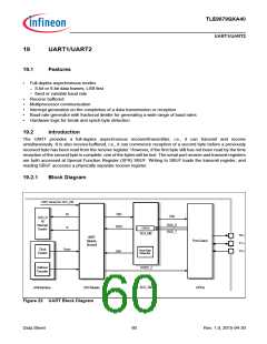
19.3
UART Modes
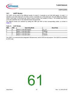
The UART can be used in four different modes. In mode 0, it operates as an 8-bit shift register. In mode 1, it
operates as an 8-bit serial port. In modes 2 and 3, it operates as a 9-bit serial port. The only difference between
mode 2 and mode 3 is the baud rate, which is fixed in mode 2 but variable in mode 3. The variable baud rate is
set by the underflow rate on the dedicated baud-rate generator.
The different modes are selected by setting bits SM0 and SM1 to their corresponding values, as shown in
Table 13.
Table 13
UART Modes
SM1
SM0
Operating Mode
Mode 0: 8-bit shift register
Baud Rate
0
0
1
1
0
1
0
1
f
PCLK/2
Variable
PCLK/64
Variable
Mode 1: 8-bit shift UART
Mode 2: 9-bit shift UART
Mode 3: 9-bit shift UART
f
The UART1 is connected to the integrated LIN transceiver, and to GPIO for test purpose. The UART2 is connected
to GPIO only.
Data Sheet
61
Rev. 1.0, 2015-04-30

 INFINEON [ Infineon ]