TLE9879QXA40
UART1/UART2
19
UART1/UART2
19.1
Features
•
Full-duplex asynchronous modes
– 8-bit or 9-bit data frames, LSB first
– fixed or variable baud rate
•
•
•
•
•
Receive buffered
Multiprocessor communication
Interrupt generation on the completion of a data transmission or reception
Baud-rate generator with fractional divider for generating a wide range of baud rates
Hardware logic for break and synch byte detection
19.2
Introduction
The UART provides a full-duplex asynchronous receiver/transmitter, i.e., it can transmit and receive
simultaneously. It is also receive-buffered, i.e., it can commence reception of a second byte before a previously
received byte has been read from the receive register. However, if the first byte still has not been read by the time
reception of the second byte is complete, one of the bytes will be lost. The serial port receive and transmit registers
are both accessed at Special Function Register (SFR) SBUF. Writing to SBUF loads the transmit register, and
reading SBUF accesses a physically separate receive register.
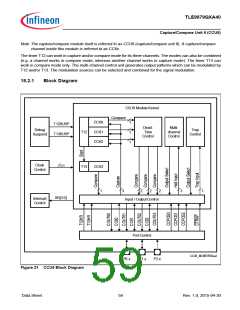
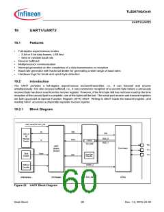
19.2.1
Block Diagram
UART disreq from SCU_DM
RI
TXD
RXD
TXD
SCU_D
M
Interrupt
Control
RXD_0
RXD_1
TI
URIOS
SCU_DM
P0.x
P1.x
P2.x
UART
Module
(Kernel)
PortControl
fUART2
Clock
Control
Baud Rate
Generator
f
BR
Address
Decoder
RXDO _2
SCU_DM
AHB Interface
SSC Module
GPIOs
Figure 22 UART Block Diagram
Data Sheet
60
Rev. 1.0, 2015-04-30

 INFINEON [ Infineon ]