OPTIREG™ SBC TLE9274QXV33
Supervision functions
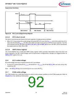
VCC1
VCC1,OV
t
tOV_filt
RO
tRD1
t
SBC Normal
SBC Restart
SBC Normal
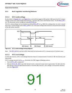
Figure 45 VCC1 overvoltage timing diagram
13.5.3
VCC1 short circuit
The short circuit protection feature for buck regulator is implemented as follows:
•
When VCC1 stays below the undervoltage threshold VRTx for more than tVCC1,SC and at the same time VS is
above the threshold VS,UV_TO, the SBC enters SBC Fail-Safe mode and turns OFF the buck regulator. The FOx
are activated and the SPI status bits VCC1_SC, VCC1_UV and BCK_SH are set. The SBC can be reactivated
by a wake event on CAN, LINx or WK
13.5.4
SMPS status register
The TLE9274QXV33 has a dedicated SMPS status register which provides information about the buck and
boost regulators. No SBC mode changes and no transceivers configurations changes are triggered when an
SMPS_STAT register bit is set.
13.6
VCC2 undervoltage
An undervoltage warning is implemented for VCC2 as follows:
•
In case VCC2 drops below the VCC2,UV,f threshold for t > tVCC2,UV, the SPI bit VCC2_UV is set and can be only
cleared via SPI
Note: The VCC2_UV flag is not set during turn-on or turn-off of VCC..
13.7
VCAN undervoltage
The CAN module has a dedicated feature to detect undervoltage condition on the VCAN supply pin. Refer to
Chapter 8.2.7 for additional information.
Datasheet
92
Rev.2.0
2022-05-06

 INFINEON [ Infineon ]