OPTIREG™ SBC TLE9274QXV33
Supervision functions
13.5
Buck regulator monitoring features
13.5.1
VCC1 undervoltage
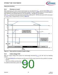
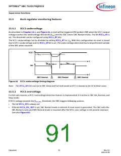
As described in Chapter 13.1, and Figure 44, a reset will be triggered (RO pulled LOW) when the VCC1 output
voltage reaches the undervoltage threshold (VRTx) and the SBC enters SBC Restart mode. The bit VCC1_UV is
set. The threshold can be configured using VCC1_RT bits.
The VCC1 undervoltage can be disabled by setting VCC1_RT to 11B. With this configuration no reset is issued
due to VCC1 undervoltage and no VCC1_UV bit is set. The under voltage detection has to be performed outside
of the SBC when required.
VCC1
VRTx
t
tRF
tRD1
RO
t
SBC Normal
SBC Restart
SBC Normal
Figure 44 VCC1 undervoltage timing diagram
Note: The VCC1_UV bit is not set in SBC Sleep and Fail-Safe mode as VCC1 is known to be 0 V in these cases.
13.5.2
VCC1 overvoltage
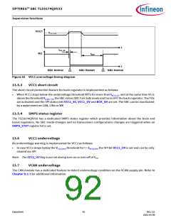
For fail-safe reasons, a VCC1 overvoltage detection feature is implemented. It is active in SBC Init, Normal, and
Stop mode.
If VCC1 voltage exceeds the VCC1,OV,r threshold, the SBC triggers following actions:
•
•
The bit VCC1_OV is always set
If the bit VCC1_OV_ RST is set, SBC Restart mode is entered. A reset event is generated. The SBC exits the
SBC Restart mode and SBC Normal mode is resumed after the VCC1 over voltage is not present anymore
(see also Figure 45)
Datasheet
91
Rev.2.0
2022-05-06

 INFINEON [ Infineon ]