OPTIREG™ SBC TLE9274QXV33
Supervision functions
13
Supervision functions
13.1
Reset function
VCC1
RO
Resetlogic
Incl. filter & delay
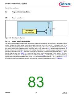
Figure 37 Reset block diagram
13.1.1
Reset output description
The reset output pin RO provides reset information to the microcontroller, for example, in the event that the
output voltage has fallen below the undervoltage threshold VRT1/2/3. In case of a reset event due to an
undervoltage on buck regulator output voltage, the reset output RO is pulled to LOW after the filter time tRF
and stays LOW as long as the reset event is present plus a reset delay time tRD1. When connecting the SBC to
battery voltage, the reset signal remains LOW initially. When the buck regulator output voltage has reached
the default reset threshold VRT1,f, the reset output RO is released to HIGH after the reset delay time tRD1 (for a
timing diagram, see also Figure 4). A reset can also occur due to a watchdog trigger failure. The reset
threshold can be adjusted via SPI, the default reset threshold is VRT1,f. The RO pin has an integrated pull-up
resistor. If a reset is triggered, it will pull LOW for buck regulator output voltage (VCC1) ≥ 1 V and for VS ≥ VPOR,f
.
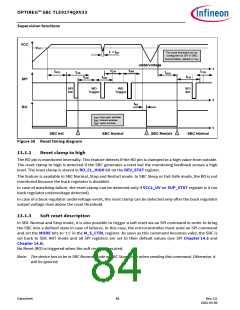
RO trigger timing regarding buck regulator undervoltage and watchdog trigger is shown in Figure 38.
Datasheet
83
Rev.2.0
2022-05-06

 INFINEON [ Infineon ]