OPTIREG™ SBC TLE9274QXV33
Supervision functions
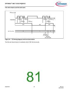
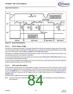
VCC
VRT1
t < tRF
The reset threshold can be
configured via SPI in SBC
Normal Mode, default is VRT1
undervoltage
t
tCW
tOW
tRD1
tCW
tLW
tRD1
tLW
tCW
tOW
SPI
RO
SPI
Init
WD
Trigger
WD
Trigger
SPI
Init
t
t
tRF
tLW= long open window
tCW= closed window
tOW= open window
SBC Init
SBC Normal
SBC Restart
SBC Normal
Figure 38 Reset timing diagram
13.1.2
Reset clamp to high
The RO pin is monitored internally. This feature detects if the RO pin is clamped to a high value from outside.
The reset clamp to high is detected if the SBC generates a reset but the monitoring feedback senses a high
level. The reset clamp is stored in RO_CL_HIGH bit on the DEV_STAT register.
The feature is available in SBC Normal, Stop and Restart mode. In SBC Sleep or Fail-Safe mode, the RO is not
monitored because the buck regulator is disabled.
In case of watchdog failure, the reset clamp can be detected only if VCC1_UV on SUP_STAT register is 0 (no
buck regulator undervoltage detected).
In case of a buck regulator undervoltage event, the reset clamp can be detected only after the buck regulator
output voltage rises above the reset threshold.
13.1.3
Soft reset description
In SBC Normal and Stop mode, it is also possible to trigger a soft reset via an SPI command in order to bring
the SBC into a defined state in case of failures. In this case, the microcontroller must send an SPI command
and set the MODE bits to ‘11’ in the M_S_CTRL register. As soon as this command becomes valid, the SBC is
set back to SBC INIT mode and all SPI registers are set to their default values (see SPI Chapter 14.5 and
Chapter 14.6).
No Reset (RO) is triggered when the soft reset is executed.
Note: The device has to be in SBC Normal mode or SBC Stop mode when sending this command. Otherwise, it
will be ignored.
Datasheet
84
Rev.2.0
2022-05-06

 INFINEON [ Infineon ]