OPTIREG™ SBC TLE9274QXV33
DC/DC regulators
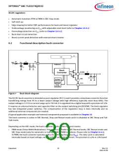
on input supply and output current range (refer to Figure 13 for more information). In PWM mode, the
buck converter is capable of a 100% duty cycle in case of low VS conditions. In order to reduce EMC, edge
shaping feature has been implemented to control the activation and deactivation of the two power
switches
•
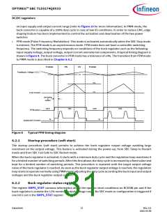
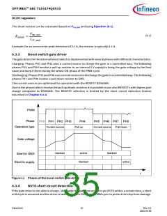
PFM mode (Pulse Frequency Modulation): This mode is activated automatically when the SBC Stop mode
is entered. The PFM mode is an asynchronous mode. PFM mode does not have a controller switching
frequency. The switching frequency depends on conditions of the buck regulator such as the following:
input supply voltage, output voltage, output current and external components. A typical timing diagram is
shown in Figure 8. The buck converter in PFM mode has a tolerance of ±4%. The transition from PFM mode
to PWM mode is described in Chapter 6.4.2
Tristate
HS
LS
Tristate
Feedback Voltage VCC 1
LVL
UCL
LCL
Coil Current
start biasing
&
oscillator
OFF
ON
OFF
ON
PFM active
Iq
Iq
Quiescent Current
Figure 8
Typical PFM timing diagram
6.2.1
Startup procedure (soft start)
The startup procedure (soft start) permits to achieve the buck regulator output voltage avoiding large
overshoot on the output voltage. This feature is activated during the power-up, from SBC Sleep to Restart
mode and from SBC Fail-Safe to SBC Restart mode.
When the buck regulator is activated, it starts with a minimum duty cycle and the regulation loop maintains it
for a limited number of switching periods. After this first phase, the duty cycle is increased by a fixed value and
kept for a limited number of switching periods. This procedure is repeated until the target output voltage
value of the buck regulator is reached. As soon as the buck regulator output voltage is reached, the regulation
loop starts to operate normally using PWM mode adjusting the duty cycle according the buck input and output
voltages and the buck regulator output current.
6.2.2
Buck regulator status register
The register SMPS_STAT contains information about the open or short conditions on BCKSW pin and if the
buck regulator is outside the 12% nominal output voltage range. No SBC mode or configuration is triggered if
one bit is set in the SMPS_STAT register.
Datasheet
31
Rev.2.0
2022-05-06

 INFINEON [ Infineon ]