OPTIREG™ SBC TLE9274QXV33
DC/DC regulators
•
•
•
•
•
•
•
Automatic transition PFM to PWM in SBC Stop mode
Soft start-up
Edge shaping for better EMC performances for buck and boost regulator
Undervoltage monitoring on VCC1 with adjustable reset level (refer to Chapter 13.5.1)
Overvoltage detection on VCC1 (refer to Chapter 13.5.2)
Buck short circuit detection
Boost current peak detection with external shunt resistor
6.2
Functional description buck converter
SPI
Logic
L1
VS
D1
Vbat
VSUP
Feedforward
C1
C2
C3
Buck
Converter
L2
BCKSW
C4
C5
GND
Bandgap
Reference
VCC1
Soft Start
Ramp
Generator
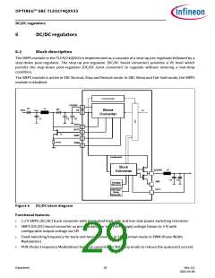
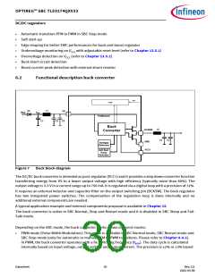
Figure 7
Buck block diagram
The DC/DC buck converter is intended as post-regulator (VCC1) and it provides a step down converter function
transferring energy from VS to a lower output voltage with high efficiency (typically more than 80%). The
output voltage is 3.3 V in a current range up to 750 mA. It is regulated via a digital loop with a precision of ±2%.
It requires an external inductor and capacitor filter on the output switching pin (BCKSW). The buck regulator
has two integrated power switches. The compensation of the regulation loop is done internally and no
additonal external components are needed.
A typical application example and external components proposal is available in Chapter 15.
The buck converter is active in SBC Normal, Stop and Restart mode and it is disabled in SBC Sleep and Fail-
Safe mode.
Depending on the SBC mode, the buck converter works in two different modes:
•
PWM mode (Pulse Width Modulation): This mode is available in SBC Normal mode, SBC Restart mode and
SBC Stop mode (only for automatic or manual PFM to PWM transitions. Please refer to Chapter 6.4.2).
In PWM, the buck converter operates with a fix switching frequency (fBCK). The duty cycle is calculated
internally based on input voltage, output voltage and output current. The precision is ±2% or ±3% based
Datasheet
30
Rev.2.0
2022-05-06

 INFINEON [ Infineon ]