TLD7002-16ES
Datasheet
9 Communication interface
9.1.11.11 CRC overview
The CRC-3 for master request (CRC[7:5]) in the master request is calculated over the Address[4:0], MRC[7:6], DLC[5:3]
and FUN[2:0]. The generator polynom is x3 + x + 1 and the seed is 0x5.
The CRC-3 for slave response (CRC[7:5]) in the slave response is calculated over the output status byte, MODE[4:3],
RC[2:1] and TER. The generator polynom is x3 + x + 1 and the seed is 0x5.
The CRC-8 for the safety byte (CRC[7:0]) for the safety byte is defined with the generator polynom according to
CRC-8-AUTOSAR and SAE J1850: 0x8e = x^8 +x^4 +x^3 +x^2 +1 and the seed is 0xFF.
The CRC-8 is used in following frames and calculated over dedicated bytes or words :
Frame
Words
DC_UPDATE
PM_CHANGE
WRITE_REG
READ_REG
DutyDycleOUT0 to DutyCycleOUT15
PowerMode and 0x00
StartADDR + Data * DLC
StartADDR + Data * DLC
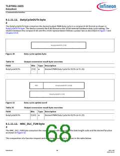
9.1.11.12 Byte Field Description
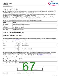
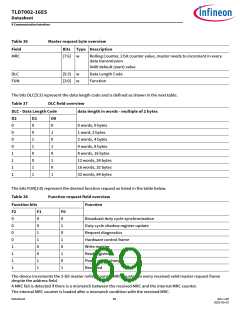
9.1.11.12. MASTER_REQ_ADDR
1
The master request address byte comprises the slave address information and a CRC[7:5] bit field to secure the data
transmission as shown in Figure 29.
Table 32
Master request byte overview
Bits Type Description
Field
Address
[4:0]
w
Slave Address
CRC
[7:5]
w
Cyclic Redundancy Check
The composition of a master request field is shown above. Bits Address[4:0] represent the slave address information
and the broadcast address as shown in table below. To avoid an incorrect arbitration of the bus in case of
disturbances, the master request frame includes 3-bit CRC[7:5] as described in CRC-3 for master requests.
Table 33
Slave address overview
Function
Slave Address
A4
0
A3
A2
A1
A0
0
0
0
0
Broadcast
N
Slave n [1..31]
Figure 29
Master request byte to address the slaves
Datasheet
67
Rev.1.00
2022-05-03

 INFINEON [ Infineon ]