TC1796
Functional Description
3.22
On-Chip Debug Support
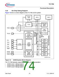
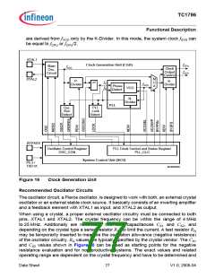
Figure 18 shows a block diagram of the TC1796 OCDS system.
TriCore
SBCU
CPU
RBCU
Watchdog
Timer
PCP2
(WDT)
M
TR[15:0]
TRCLK
U
X
DMA
Controller
Cerberus
(Bus Bridge)
OCDS
System
System
Control Unit
(OSCU)
Peripheral
Bus
SPB
TDI
Peripheral
Unit 1
TDO
TMS
TCK
TRST
JTAG
Debug
Interface
(JDI)
JTAG
SPB
Peripheral
Unit m
Controller
RPB
Peripheral
Unit 1
Multi Core
Break
BRKIN
RPB
Peripheral
Unit n
Switch
BRKOUT
(MCBS)
MCB05756_mod
Figure 18
OCDS System Block Diagram
The TC1796 basically supports three levels of debug operation:
•
•
•
OCDS Level 1 debug support
OCDS Level 2 debug support
OCDS Level 3 debug support
Data Sheet
74
V1.0, 2008-04

 INFINEON [ Infineon ]