TC39x BC/BD-Step
Electrical SpecificationInter-IC (I2C) Interface Timing
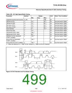
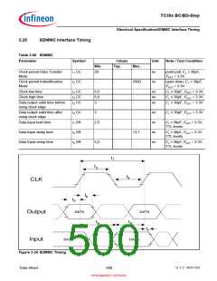
Table 3-64 I2C Fast Mode Timing
Parameter
Symbol
Values
Typ.
Unit
Note / Test Condition
Min.
Max.
Fall time of both SDA and SCL t1
20+0.1*Cb
-
300
ns
Measured with a pull-
up resistor of 4.7 kohms
at each of the SCL and
SDA line
Capacitive load for each bus line Cb SR
-
-
-
400
-
pF
µs
Bus free time between a STOP t10
1.3
Measured with a pull-
up resistor of 4.7 kohms
at each of the SCL and
SDA line
and ATART condition
Rise time of both SDA and SCL t2
20+0.1*Cb
-
-
-
-
-
-
-
-
300
ns
µs
ns
µs
µs
µs
µs
µs
Measured with a pull-
up resistor of 4.7 kohms
at each of the SCL and
SDA line
Data hold time
t3
t4
t5
t6
t7
t8
0
-
-
-
-
-
-
-
Measured with a pull-
up resistor of 4.7 kohms
at each of the SCL and
SDA line
Data set-up time
100
1.3
0.6
0.6
0.6
0.6
Measured with a pull-
up resistor of 4.7 kohms
at each of the SCL and
SDA line
Low period of SCL clock
High period of SCL clock
Measured with a pull-
up resistor of 4.7 kohms
at each of the SCL and
SDA line
Measured with a pull-
up resistor of 4.7 kohms
at each of the SCL and
SDA line
Hold time for the (repeated)
START condition
Measured with a pull-
up resistor of 4.7 kohms
at each of the SCL and
SDA line
Set-up time for (repeated)
START condition
Measured with a pull-
up resistor of 4.7 kohms
at each of the SCL and
SDA line
Set-up time for STOP condition t9
Measured with a pull-
up resistor of 4.7 kohms
at each of the SCL and
SDA line
Data Sheet
498
V 1.2, 2021-03
OPEN MARKET VERSION

 INFINEON [ Infineon ]