TC39x BC/BD-Step
Electrical SpecificationQSPI Timings, Master and Slave Mode
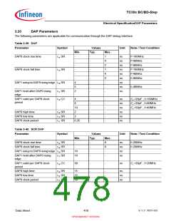
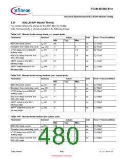
3.22
QSPI Timings, Master and Slave Mode
This section defines the timings for the QSPI in the TC39x.
It is assumed that SCLKO, MTSR, and SLSO pads have the same pad settings:
Note:Pad asymmetry is already included in the following timings.
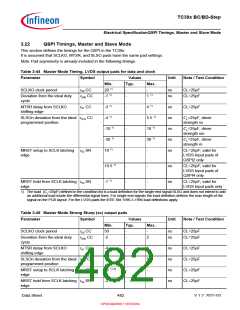
Table 3-44 Master Mode Timing, LVDS output pads for data and clock
Parameter
Symbol
Values
Typ.
Unit
Note / Test Condition
Min.
20 1)
-1 1)
Max.
-
1 1)
SCLKO clock period
t
t
50 CC
-
-
ns
ns
CL=25pF
CL=25pF
Deviation from the ideal duty
cycle
500 CC
MTSR delay from SCLKO
shifting edge
t
51 CC
-3 1)
-
-
-
-
-
4 1)
ns
ns
ns
ns
ns
CL=25pF
SLSOn deviation from the ideal t510 CC
programmed position
-4 1)
5.5 1)
10 1)
30 1)
-
CL=25pF, driver
strength ss
-10 1)
-30 1)
18 1)
CL=25pF, driver
strength sm
CL=25pF, driver
strength m
MRST setup to SCLK latching
edge
t
52 SR
CL=25pF; valid for
LVDS Input pads of
QSPI2 only
19.5 1)
-
-
-
-
ns
ns
CL=25pF; valid for
LVDS Input pads of
QSPI4 only
MRST hold from SCLK latching t53 SR
-1 1)
CL=25pF; valid for
edge
LVDS Input pads only
1) The load (CL=25pF) defined in the condition list is a load definition for the single end signal SLSO and does not intend to add
an additional load inside the differential signal lines. For single end signals the load definition defines the max length of the
signal on the PCB layout. For the LVDS pads the IEEE Std 1596.3-1996 load definitions apply.
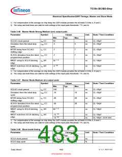
Table 3-45 Master Mode Strong Sharp (ss) output pads
Parameter
Symbol
Values
Typ.
Unit
Note / Test Condition
Min.
50
Max.
SCLKO clock period
t
t
50 CC
-
-
-
ns
ns
CL=25pF
CL=25pF
Deviation from the ideal duty
cycle
500 CC
-2
2
MTSR delay from SCLKO
shifting edge
t
51 CC
-4
-
-
-
-
5
5
-
ns
ns
ns
ns
CL=25pF
CL=25pF
CL=25pF
CL=25pF
SLSOn deviation from the ideal t510 CC
programmed position
-4
MRST setup to SCLK latching
edge
t
52 SR
25 1) 2)
-2 1)2)
MRST hold from SCLK latching t53 SR
-
edge
Data Sheet
482
V 1.2, 2021-03
OPEN MARKET VERSION

 INFINEON [ Infineon ]