TC39x BC/BD-Step
Electrical SpecificationOperating Conditions
3.4
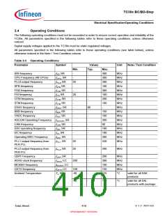
Operating Conditions
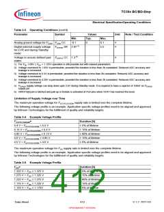
The following operating conditions must not be exceeded in order to ensure correct operation and reliability of the
TC39x. All parameters specified in the following tables refer to these operating conditions, unless otherwise
noticed.
Digital supply voltages applied to the TC39x must be static regulated voltages.
All parameters specified in the following tables refer to these operating conditions (see table below), unless
otherwise noticed in the Note / Test Condition column.
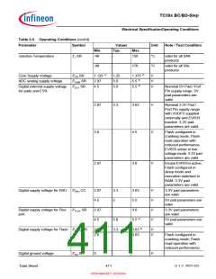
Table 3-3 Operating Conditions
Parameter
Symbol
Values
Typ.
Unit
Note / Test Condition
Min.
Max.
300
300
300
100
300
100
200
100
-
SRI frequency
f
f
f
f
f
f
f
f
f
f
f
f
f
f
f
f
f
SRI SR
-
-
MHz
MHz
MHz
MHz
MHz
MHz
MHz
MHz
MHz
MHz
MHz
MHz
MHz
MHz
MHz
MHz
MHz
CPU Frequency (All CPUs)
PLL0 output frequency
SPB frequency
CPUx SR
PLL0 SR
SPB SR
FSI2 SR
FSI SR
-
-
20
-
-
-
FSI2 frequency
-
-
FSI frequency
20
-
-
GTM frequency
GTM SR
STM SR
ERAY SR
BBB SR
ADC SR
ASCLINx SR
CAN SR
EBU SR
I2C SR
-
STM frequency
-
-
ERAY frequency
-
80
-
BBB frequency
-
150
160
200
80
VADC frequency
-
-
ASCLIN Operating Frequency
CAN frequency
-
-
-
-
EBU operating frequency
I2C frequency
-
-
160
100
200
320
-
-
Operating MSC Frequency
MSC SR
PLL1 SR
-
-
PLL1 output frequency from
PER PLL
20
-
PLL2 output frequency from
PER PLL
f
PLL2 SR
20
-
200
MHz
QSPI Frequency
f
f
f
f
QSPI SR
-
-
-
-
-
-
200
300
100
150
125
MHz
MHz
MHz
MHz
°C
ADAS clock frequency
MCANH frequency
GETH frequency
ADAS CC
MCANH CC
GETH CC
200
-
100
-40
Ambient Temperature
TA SR
valid for all SAK
products
-40
-
150
°C
valid for all SAL
products with package
Data Sheet
410
V 1.2, 2021-03
OPEN MARKET VERSION

 INFINEON [ Infineon ]