IRL7472L1TRPbF
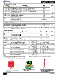
Absolute Maximum Ratings
Symbol
Parameter
Max.
645
456
68
Units
ID @ TC = 25°C
Continuous Drain Current, VGS @ 10V (Silicon Limited)
ID @ TC = 100°C Continuous Drain Current, VGS @ 10V (Silicon Limited)
ID @ TA = 25°C Continuous Drain Current, VGS @ 10V (Silicon Limited)
ID @ TC = 25°C Continuous Drain Current, VGS @ 10V (Package Limited)
A
375
1500
IDM
Pulsed Drain Current
Maximum Power Dissipation
Maximum Power Dissipation
Linear Derating Factor
A
PD @TC = 25°C
PD @TA = 25°C
341
W
3.8
0.025
W/°C
V
Gate-to-Source Voltage
Operating Junction and
± 20
VGS
TJ
-55 to + 175
°C
Storage Temperature Range
TSTG
Avalanche Characteristics
EAS (Thermally limited)
308
765
Single Pulse Avalanche Energy
Single Pulse Avalanche Energy
Avalanche Current
mJ
EAS (Thermally limited)
IAR
A
mJ
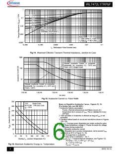
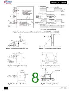
See Fig.15,16, 23a, 23b
EAR
Repetitive Avalanche Energy
Thermal Resistance
Symbol
Parameter
Typ.
–––
12.5
20
Max.
40
Units
Junction-to-Ambient
RJA
Junction-to-Ambient
Junction-to-Ambient
Junction-to-Case
Junction-to-PCB Mounted
–––
–––
0.44
–––
RJA
°C/W
RJA
RJC
RJA-PCB
–––
1.0
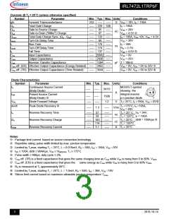
Static @ TJ = 25°C (unless otherwise specified)
Symbol
V(BR)DSS
Parameter
Min. Typ. Max. Units
Conditions
VGS = 0V, ID = 250µA
Drain-to-Source Breakdown Voltage
Breakdown Voltage Temp. Coefficient
Static Drain-to-Source On-Resistance
40
––– –––
V
–––
30 ––– mV/°C Reference to 25°C, ID = 5.0mA
V(BR)DSS/TJ
RDS(on)
––– 0.34 0.45
––– 0.52 0.70
VGS = 10V, ID = 195A
m
V
GS = 4.5V, ID = 98A
VGS(th)
IDSS
Gate Threshold Voltage
1.0
1.7 2.5
V
VDS = VGS, ID = 250µA
––– ––– 1.0
––– ––– 150
––– ––– 100
––– ––– -100
––– 1.0 –––
VDS = 40V, VGS = 0V
Drain-to-Source Leakage Current
µA
VDS = 40V, VGS = 0V, TJ = 125°C
IGSS
Gate-to-Source Forward Leakage
Gate-to-Source Reverse Leakage
Internal Gate Resistance
VGS = 20V
GS = -20V
nA
V
RG
Notes:
Mounted on minimum footprint full size board with metalized
back and with small clip heatsink.
TC measured with thermocouple mounted to top (Drain) of part.
Used double sided cooling , mounting pad with large heatsink.
Mounted to a PCB with small clip
heatsink (still air)
Mounted on minimum footprint full size
board with metalized back and with
small clip heatsink (still air)
Surface mounted on 1 in. square Cu
board (still air).
2
2016-10-14

 INFINEON [ Infineon ]