CoolSET®-F3R
ICE3BR0665JF
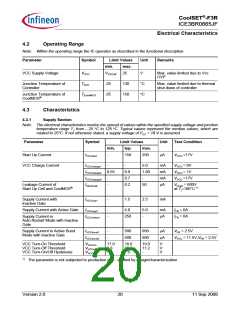
Functional Description
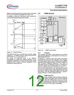
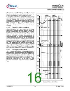
After entering Active Burst Mode, a burst flag is set and
the internal bias is switched off in order to reduce the
current consumption of the IC to approx. 500uA.
VFB
Leaving
Active Burst
Mode
Entering
Active Burst
Mode
It needs the application to enforce the VCC voltage
above the Undervoltage Lockout level of 10.5V such
that the Startup Cell will not be switched on
accidentally. Or otherwise the power loss will increase
drastically. The minimum VCC level during Active Burst
Mode depends on the load condition and the
application. The lowest VCC level is reached at no load
condition.
4.5V
3.6V
3.1V
1.22V
Blanking Timer
t
3.7.2.2
Working in Active Burst Mode
20ms Blanking Time
After entering the Active Burst Mode, the FB voltage
rises as VOUT starts to decrease, which is due to the
inactive PWM section. The comparator C6a monitors
the FB signal. If the voltage level is larger than 3.6V, the
internal circuit will be activated; the Internal Bias circuit
resumes and starts to provide switching pulse. In
Active Burst Mode the gate G10 is released and the
current limit is reduced to 0.26V. In one hand, it can
reduce the conduction loss and the other hand, it can
reduce the audible noise. If the load at VOUT is still kept
unchanged, the FB signal will drop to 3.1V. At this level
the C6b deactivates the internal circuit again by
switching off the internal Bias. The gate G11 is active
again as the burst flag is set after entering Active Burst
Mode. In Active Burst Mode, the FB voltage is changing
like a saw tooth between 3.1V and 3.6V (see figure 17).
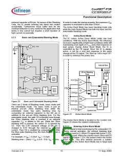
VCS
t
t
t
t
t
Current limit level
during Active Burst
Mode
1.0V
0.26V
VVCC
3.7.2.3
Leaving Active Burst Mode
The FB voltage will increase immediately if there is a
high load jump. This is observed by the comparator C4.
As the current limit is appr. 26% during Active Burst
Mode, a certain load jump is needed so that the FB
signal can exceed 4.5V. At that time the comparator C4
resets the Active Burst Mode control which in turn
blocks the comparator C12 by the gate G10. The
maximum current can then be resumed to stabilize
VOUT.
10.0V
IVCC
4mA
500uA
VOUT
Max. Ripple < 1%
Figure 24
Signals in Active Burst Mode
Version 2.0
16
11 Sep 2008

 INFINEON [ Infineon ]