CoolSET®-F3R
ICE3BR0665JF
Functional Description
external capacitor at BA pin. By means of this Blanking In order to make the startup properly, the maximum CBK
Time, the IC avoids entering into these two modes capacitor is restricted to less than 0.65uF.
accidentally. Furthermore those buffer time for the
overload detection is very useful for the application that
works in low current but requires a short duration of
high current occasionally.
The Active Burst Mode has basic blanking mode only
while the Auto Restart Mode has both the basic and the
extendable blanking mode.
3.7.2
Active Burst Mode
3.7.1
Basic and Extendable Blanking Mode
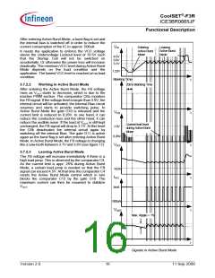
The IC enters Active Burst Mode under low load
conditions. With the Active Burst Mode, the efficiency
increases significantly at light load conditions while still
maintaining a low ripple on VOUT and a fast response on
load jumps. During Active Burst Mode, the IC is
controlled by the FB signal. Since the IC is always
active, it can be a very fast response to the quick
change at the FB signal. The Start up Cell is kept OFF
in order to minimize the power loss.
BA
5.0V
CBK
#
IBK
0.9V
1
S1
G2
Internal Bias
Current
C3
Spike
Blanking
30us
4.0V
4.5V
Limiting
20 ms Blanking
Time
&
&
G10
20ms
Blanking
Time
G5
Auto
Restart
Mode
C4
C5
4.5V
C4
Active
FB
&
FB
Active
Burst
Mode
Burst
Mode
20ms
Blanking
Time
G6
C5
&
G6
1.22V
1.22V
3.6V
3.1V
Control Unit
C6a
C6b
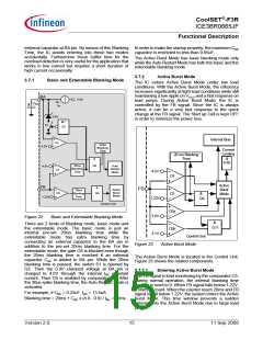
Figure 22
Basic and Extendable Blanking Mode
&
G11
There are 2 kinds of Blanking mode; basic mode and
the extendable mode. The basic mode is just an
internal pre-set 20ms blanking time while the
extendable mode has extra blanking time by
connecting an external capacitor to the BA pin in
addition to the pre-set 20ms blanking time. For the
extendable mode, the gate G5 is blocked even though
the 20ms blanking time is reached if an external
capacitor CBK is added to BA pin. While the 20ms
blanking time is passed, the switch S1 is opened by
G2. Then the 0.9V clamped voltage at BA pin is
charged to 4.0V through the internal IBK constant
current. Then G5 is enabled by comparator C3. After
the 30us spike blanking time, the Auto Restart Mode is
activated.
Control Unit
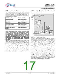
Figure 23
Active Burst Mode
The Active Burst Mode is located in the Control Unit.
Figure 23 shows the related components.
3.7.2.1
Entering Active Burst Mode
The FB signal is kept monitoring by the comparator C5.
During normal operation, the internal blanking time
counter is reset to 0. When FB signal falls below 1.22V,
it starts to count. When the counter reach 20ms and FB
signal is still below 1.22V, the system enters the Active
Burst Mode. This time window prevents a sudden
entering into the Active Burst Mode due to large load
jumps.
For example, if CBK = 0.22uF, IBK = 13.5uA
Blanking time = 20ms + CBK x (4.0 - 0.9) / IBK = 70ms
Version 2.0
15
11 Sep 2008

 INFINEON [ Infineon ]