CoolSET®-F3R
ICE3BR0665JF
Functional Description
3.7.3
Protection Modes
3.7.3.1
Auto Restart mode with extended
blanking time
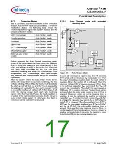
The IC provides Auto Restart Mode as the protection
feature. Auto Restart mode can prevent the SMPS from
destructive states. The following table shows the
relationship between possible system failures and the
chosen protection modes.
BA
5.0V
CBK
#
IBK
VCC Overvoltage
Overtemperature
Overload
Auto Restart Mode
Auto Restart Mode
Auto Restart Mode
Auto Restart Mode
Auto Restart Mode
Auto Restart Mode
Auto Restart Mode
0.9V
1
S1
G2
Open Loop
VCC Undervoltage
Short Optocoupler
C3
C4
Spike
Blanking
30us
4.0V
External auto restart
enable
&
Before entering the Auto Restart protection mode,
some of the protections can have extended blanking
time to delay the protection and some needs to fast
react and will go straight to the protection. Overload
and open loop protection are the one can have
extended blanking time while Vcc Overvoltage, Over
temperature, Vcc Undervoltage, short opto-coupler
and external auto restart enable will go to protection
right away.
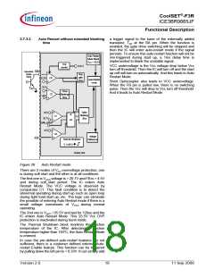
After the system enters the Auto-restart mode, the IC
will be off. Since there is no more switching, the Vcc
voltage will drop. When it hits the Vcc turn off threshold,
the start up cell will turn on and the Vcc is charged by
the startup cell current to Vcc turn on threshold. The IC
is on and the startup cell will turn off. At this stage, it will
enter the startup phase (soft start) with switching
cycles. After the Start Up Phase, the fault condition is
checked. If the fault condition persists, the IC will go to
auto restart mode again. If, otherwise, the fault is
removed, normal operation is resumed.
20ms
Blanking
Time
G5
Auto
Restart
Mode
4.5V
FB
Control Unit
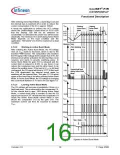
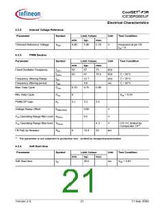
Figure 25
Auto Restart Mode
In case of Overload or Open Loop, the FB exceeds
4.5V which will be observed by comparator C4. Then
the internal blanking counter starts to count. When it
reaches 20ms, the switch S1 is released. Then the
clamped voltage 0.9V at VBA can increase. When there
is no external capacitor CBK connected, the VBA will
reach 4.0V immediately. When both the input signals at
AND gate G5 is positive, the Auto Restart Mode will be
activated after the extra spike blanking time of 30us is
elapsed. However, when an extra blanking time is
needed, it can be achieved by adding an external
capacitor, CBK. A constant current source of IBK will start
to charge the capacitor CBK from 0.9V to 4.0V after the
switch S1 is released. The charging time from 0.9V to
4.0V are the extendable blanking time. If CBK is 0.22uF
and IBK is 13.5uA, the extendable blanking time is
around 50ms and the total blanking time is 70ms. In
combining the FB and blanking time, there is a blanking
window generated which prevents the system to enter
Auto Restart Mode due to large load jumps.
Version 2.0
17
11 Sep 2008

 INFINEON [ Infineon ]