Quasi-Resonant, 800V CoolSET™ in DS0-12 Package
Electrical Characteristics
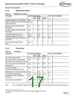
4.3.8
Active Burst Mode
Table 13
Digital Zero Crossing
Parameter
Symbol
Unit Test Condition
Limit Values
min. typ.
max.
Feedback voltage for entering Active
VFBEB
-
-
1.25
7
-
-
V
Minimum Up/down value for entering
Active Burst Mode
NZC_ABM
Blanking time for entering Active
Burst Mode
tBEB
-
-
24
-
-
ms
V
Feedback voltage for leaving Active
Burst Mode
VFBLB
4.5
Feedback voltage for burst-on
Feedback voltage for burst-off
VFBBOn
VFBBOff
fsB
-
3.6
3.0
52
-
V
-
-
V
Fixed Switching Frequency in Active
Burst Mode
39
65
kHz
Max. Duty Cycle in Active Burst
Mode
DmaxB
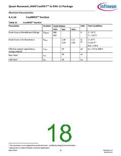
4.3.9
Protection
Table 14
Protection
Parameter
Symbol
Unit Test Condition
Limit Values
min. typ.
max.
26.0
-
VCC overvoltage threshold
VVCCOVP 24.0 25.0
V
V
Over Load or Open Loop Detection
threshold for OLP protection at FB pin
VFBOLP
tOLP_B
VZCOVP
-
4.5
30
Over Load or Open Loop Protection
Blanking Time
20
44
ms
V
Output Overvoltage
3.55 3.7
3.84
detectionthreshold at the ZC pin
Blanking time for Output Overvoltage
Threshold for short winding
tZCOVP
VCSSW
tCSSW
-
100
-
μs
V
1.63 1.68
1.78
-
Blankingtime forshort-windding
protection
-
190
140
ns
Over temperature protection1
TjCon
130
150
°C
Note:
The trend of all the voltage levels in the Control Unit is the same regarding the deviation except VVCCOVP
1 The parameter is not subjected to production test - verified by design/characterization
Data Sheet 17
Revision 1.0
2016-05-12

 INFINEON [ Infineon ]