Quasi-Resonant, 800V CoolSET™ in DS0-12 Package
Electrical Characteristics
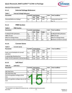
4.3.2
Internal Voltage Reference
Table 7
Internal Voltage Reference
Parameter
Symbol
Unit Test Condition
Limit Values
min. typ.
max.
Trimmed Reference Voltage
VREF
4.80
5.00
5.20
V
measured at pin FB
IFB = 0
4.3.3
PWM Section
Table 8
PWM Section
Parameter
Symbol
Unit Test Condition
Limit Values
min. typ.
max.
Feedback Pull-Up Resistor
PWM-OP Gain
Feedback Pull-Up Resistor
RFB
14
23
33
-
kΩ
-
PWM-OP Gain
GPWM
VPWM
tOnMax
3.18 3.3
Offset for Voltage Ramp
Maximum on time in normal operation
Offset for Voltage Ramp
0.6
22
0.7
30
-
V
Maximum on time in normal
41
μs
4.3.4
Current Sense
Table 9
Current sense
Parameter
Symbol
Unit Test Condition
Limit Values
min. typ.
0.97 1.03
max.
Peak current limitation in normal
operation
VCSth
1.09
V
Leading Edge Blanking time
tLEB
200
330
460
ns
V
Peak Current Limitation in Active Burst
VCSB
0.29 0.34
0.39
4.3.5
Soft Start
Table 10
Soft Start
Parameter
Symbol
Unit Test Condition
Limit Values
min. typ.
max.
Soft-Start time
tSS
8.5
12
3
-
-
-
ms
ms
V
Soft-start time step
-
-
1
Internal regulation voltage at first
step
VSS1
1.76
1
Internal regulation voltage step at soft
start
VSS_S
-
0.56
-
V
1 The parameter is not subjected to production test - verified by design/characterization
Data Sheet 15
Revision 1.0
2016-05-12

 INFINEON [ Infineon ]