CCM-PFC
ICE2PCS06/G
Functional Description
.
VOUT
VOUT,Rated
108%
100%
Normal Control
VOUT =rated
Window Detect
Max Vcomp current
VOUT
20%
95%rated
83%rated
t
Supply
related
UVLO / IBOP
t
Current
related
PCL / SOC
Level-shifted VCOMP
Output
related
av(IIN)
OLP
OVP
OLP
VCOMP
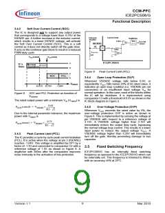
Figure 6
3.4.1
Protection Features
Input Brown-Out Protection (IBOP)
t
Brown-out occurs when the input voltage VIN falls below
the minimum input voltage of the design (i.e. 85V for
universal input voltage range) and the VCC has not
entered into the VCCUVLO level yet. For a system without
IBOP, the boost converter will increasingly draw a
higher current from the mains at a given output power
which may exceed the maximum design values of the
input current.
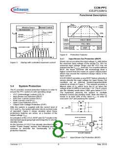
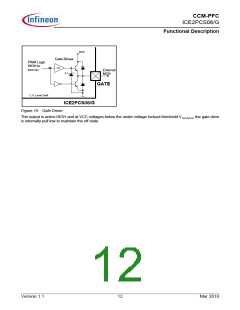
Figure 5
Startup with controlled maximum current
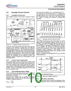
ICE2PCS06/G provides a new IBOP feature whereby it
senses directly the input voltage for Input Brown-Out
condition via an external resistor/capacitor/diode
network as shown in Figure 7. This network provides a
filtered value of VIN which turns the IC on when the
voltage at pin 4 (VINS) is more than 1.5V. The IC enters
into the standby mode when VINS goes below 0.71V.
The hysteresis prevents the system to oscillate
between normal and standby mode. Note also that VIN
needs to at least 20% of the rated VOUT in order to
overcome OLP and powerup the system.
3.4
System Protection
The IC provides several protection features in order to
ensure the PFC system in safe operating range:
•
•
•
•
•
•
VCC Undervoltage Lockout (UVLO)
Input Brown-out Detection (IBOP)
Soft Over Current Control (SOC)
Peak Current Limit (PCL)
Open-Loop Detection (OLP)
Output Over-Voltage Protection (OVP)
D2 ... D5
Vin
C1
After the system is supplied with the correct level of
VCC and VIN, the system will enter into its normal mode
of operation. Figure 6 shows situation when these
protections features are active, as a function of the
85 ... 265 VAC
output voltage VOUT
.
Brown-Out Detection
R8
An activation of the UVLO, IBOP and OLP results in the
internal fault signal going high and brings the IC into the
standby mode.
0.71V
D7
C4
VINS
80k
brown-out
S
R
As the function of UVLO has already described in the
earlier “Power Supply” section, the following sections
continue to describe the functionality of these
protection features.
C5
1.5V
C6
R9
3.5V
ICE2PCS06/G
Input Brown-Out Protection (IBOP)
Figure 7
Version 1.1
8
Mar 2010

 INFINEON [ Infineon ]