BTS7040-1EPA
PROFET™ +2 12V
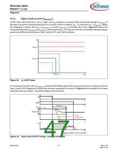
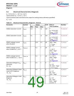
Diagnosis
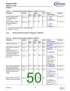
Table 20 Electrical Characteristics: Diagnosis - PROFET™ (continued)
Parameter
Symbol
Values
Typ.
5
Unit Note or
Test Condition
Number
Min.
Max.
1)
SENSE Disable Time
tsIS(OFF)
–
20
µs
µs
P_9.6.1.8
From DEN falling
edge to IIS = IIS(OFF)
See Figure 40
1)
SENSE Settling Time after
Load Change
tsIS(LC)
–
–
5
20
P_9.6.1.9
from IL = IL(CAL)_L to
IL = IL(CAL) (see
ΔkILIS(NOM)
)
See Figure 40
1)
SENSE Settling Time after
Load Change with Small
Load Current
tsIS(LC)_SLC
250
400
µs
P_9.6.1.14
DEN = “high”
from Load Change
toIIS = IL /(kILIS @ IL)
from IL(CAL) to
IL(CAL)_OL
1) Not subject to production test - specified by design.
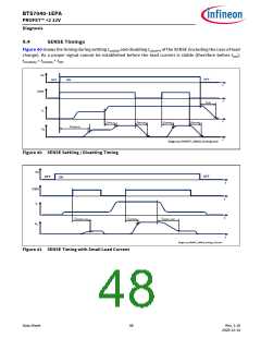
9.6
Electrical Characteristics Diagnosis - Power Output Stages
VS = 6 V to 18 V, TJ = -40 °C to +150 °C
Typical values: VS = 13.5 V, TJ = 25 °C
Typical resistive load connected to the output for testing (unless otherwise specified):
RL = 3.3 Ω
9.6.1
Diagnosis Power Output Stage - 40 mΩ
Table 21 Electrical Characteristics: Diagnosis - 40 mΩ
Parameter
Symbol
Values
Typ.
6
Unit Note or
Test Condition
Number
Min.
Max.
Open Load Output Current IL(OL)_4u
at IIS = 4 µA
1
11
mA
IIS = IIS(OL) = 4 µA
See Figure 34
P_9.7.6.1
P_9.7.6.6
P_9.7.6.8
P_9.7.6.9
P_9.7.6.12
Current Sense Ratio at
IL = IL02
kILIS02
kILIS04
kILIS05
kILIS08
-26.0% 1750
-23.5% 1750
-20.5% 1750
-19.0% 1750
+26.0%
+23.5%
+20.5%
+19.0%
IL02 = 20 mA
IL04 = 50 mA
IL05 = 100 mA
IL08 = 250 mA
Current Sense Ratio at
IL = IL04
Current Sense Ratio at
IL = IL05
Current Sense Ratio at
IL = IL08
Data Sheet
51
Rev. 1.10
2020-12-14

 INFINEON [ Infineon ]