BTS7040-1EPA
PROFET™ +2 12V
Application Information
10
Application Information
Note:
10.1
The following information is given as a hint for the implementation of the device only and shall not
be regarded as a description or warranty of a certain functionality, condition or quality of the device.
Application Setup
VBAT
ZWIRE
Optional
Optional
CVSGND
CVS
RGND
T1
Logic Supply
VDD
GND
VS
GPIO
RIN
IN
OUT
GPIO
RDEN
DEN
COUT0
PROFET™ +2
12V
Microcontroller
DZ2
CVS2
ADC
VSS
RADC
RIS_PROT
IS
CSENSE
DZ1
Logic GND
Power GND
Optional
Chassis GND
*See Chapter 1 „Potential Applications“
App_1CH_INTD IO_CVG.emf
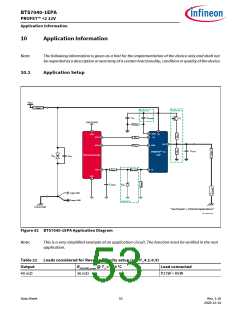
Figure 42 BTS7040-1EPA Application Diagram
Note:
This is a very simplified example of an application circuit. The function must be verified in the real
application.
Table 22 Loads considered for Reverse Polarity setup (see P_4.1.0.5)
Output
RDS(ON),max @ TJ = 150 °C
Load connected
40 mΩ
36 mΩ
P27W + R5W
Data Sheet
53
Rev. 1.10
2020-12-14

 INFINEON [ Infineon ]