BTS7040-1EPA
PROFET™ +2 12V
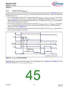
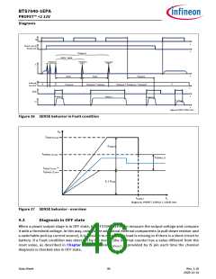
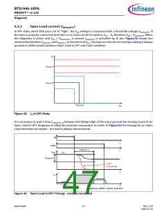
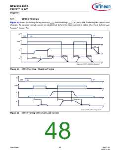
Diagnosis
9.5
Electrical Characteristics Diagnosis
VS = 6 V to 18 V, TJ = -40 °C to +150 °C
Typical values: VS = 13.5 V, TJ = 25 °C
Typical resistive load connected to the output for testing (unless otherwise specified):
RL = 3.3 Ω
Table 19 Electrical Characteristics: Diagnosis - General
Parameter
Symbol
Values
Typ.
–
Unit Note or
Test Condition
Number
Min.
Max.
1)
SENSE Saturation Current
IIS(SAT)
4.4
15
mA
P_9.6.0.13
VS = 8 V to 18 V
RSENSE = 1.2 kΩ
See Figure 37
1)
SENSE Saturation Current
IIS(SAT)
4.1
–
15
mA
P_9.6.0.14
VS = 6 V to 18 V
RSENSE = 1.2 kΩ
See Figure 37
SENSE Leakage Current
when Disabled
IIS(OFF)
–
–
0.01
0.2
0.5
1
µA
µA
DEN = “low”
IL ≥ IL(NOM)
VIS = 0 V
1)
P_9.6.0.2
P_9.6.0.3
SENSE Leakage Current
IIS(EN)_85
when Enabled at TJ ≤ 85 °C
TJ ≤ 85 °C
DEN = “high”
IL = 0 A
See Figure 34
SENSE Leakage Current
when Enabled at TJ = 150 °C
IIS(EN)_150
–
–
–
–
0.2
0.5
0.5
0.5
1
1
1
1
µA
V
TJ = 150 °C
DEN = “high”
IL = 0 A
See Figure 34
1)
P_9.6.0.4
P_9.6.0.6
P_9.6.0.7
P_9.6.0.8
Saturation Voltage in kILIS
Operation
(VS - VIS)
VSIS_k
VS = 6 V
IN = DEN = “high”
IL ≤ 1.2 * IL(NOM)
1)
Saturation Voltage in Open VSIS_OL
Load at OFF Diagnosis
(VS - VIS)
V
VS = 6 V
IN = “low”
DEN = “high”
1)
Saturation Voltage in Fault VSIS_F
V
Diagnosis
VS = 6 V
(VS - VIS)
IN = “low”
DEN = “high”
counter >0
Data Sheet
49
Rev. 1.10
2020-12-14

 INFINEON [ Infineon ]