BTS7040-1EPA
PROFET™ +2 12V
Diagnosis
Table 19 Electrical Characteristics: Diagnosis - General (continued)
Parameter
Symbol
Values
Typ.
Unit Note or
Test Condition
Number
Min.
Max.
Power Supply to IS Pin
Clamping Voltage at
TJ = -40 °C
VSIS(CLAMP)_- 33
36.5
42
V
IIS = 1 mA
P_9.6.0.9
TJ = -40 °C
See Figure 17
2)
40
Power Supply to IS Pin
Clamping Voltage at
TJ ≥ 25 °C
VSIS(CLAMP)_25 35
38
44
V
P_9.6.0.10
IIS = 1 mA
TJ ≥ 25 °C
See Figure 17
1) Not subject to production test - specified by design.
2) Tested at TJ = 150°C.
9.5.1
Electrical Characteristics Diagnosis - PROFET™
Table 20 Electrical Characteristics: Diagnosis - PROFET™
Parameter
Symbol
Values
Typ.
5.5
Unit Note or
Test Condition
Number
Min.
Max.
SENSE Fault Current
IIS(FAULT)
IIS(OLOFF)
tIS(FAULT)_D
4.4
10
mA
mA
µs
See Figure 37 and P_9.6.1.1
Figure 38
SENSE Open Load in OFF
Current
1.9
–
2.5
3.5
–
See Figure 37 and P_9.6.1.2
Figure 38
1)
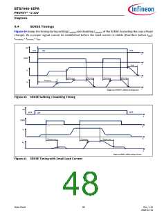
SENSE Delay Time at
Channel Switch ON after
Last Fault Condition
500
P_9.6.1.3
See Figure 35
SENSE Open Load in OFF
Delay Time
tIS(OLOFF)_D 30
70
120
µs
VDS < VOL(OFF)
from IN falling
edge to IIS =
P_9.6.1.4
IS(OLOFF),MIN * 0.9
DEN = “high”
counter = 0
See Figure 39
Open Load VDS Detection
Threshold in OFF State
VDS(OLOFF)
tsIS(ON)
1.3
–
1.8
5
2.3
20
V
See Figure 38
P_9.6.1.5
P_9.6.1.6
SENSE Settling Time with
Nominal Load Current
Stable
µs
IL = IL(CAL)
from DEN rising
edge to IIS = IL /
(kILIS,MAX @ IL) * 0.9
See Figure 40
1)
SENSE Settling Time with
Small Load Current Stable
tsIS(ON)_SLC
–
–
60
µs
P_9.6.1.13
IL = IL(CAL)_OL
from DEN rising
edge to IIS = IL /
(kILIS,MAX @ IL) * 0.9
Data Sheet
50
Rev. 1.10
2020-12-14

 INFINEON [ Infineon ]