BTS7040-1EPA
PROFET™ +2 12V
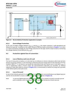
Protection
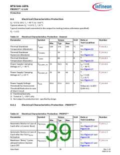
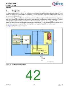
8.6
Electrical Characteristics Protection
VS = 6 V to 18 V, TJ = -40 °C to +150 °C
Typical values: VS = 13.5 V, TJ = 25 °C
Typical resistive load connected to the output for testing (unless otherwise specified):
RL = 3.3 Ω
Table 15 Electrical Characteristics: Protection - General
Parameter
Symbol
Values
Typ.
175
Unit Note or
Test Condition
Number
Min.
Max.
1)2)
Thermal Shutdown
Temperature (Absolute)
TJ(ABS)
150
200
°C
P_8.6.0.1
P_8.6.0.2
P_8.6.0.3
P_8.6.0.6
See Figure 22
3)
Thermal Shutdown
Hysteresis (Absolute)
THYS(ABS)
TJ(DYN)
–
–
30
–
K
See Figure 22
3)
Thermal Shutdown
Temperature (Dynamic)
80
–
K
See Figure 23
Power Supply Clamping
Voltage at TJ = -40 °C
VS(CLAMP)_-40 33
36.5
42
V
IVS = 5 mA
TJ = -40 °C
See Figure 17
2)
Power Supply Clamping
Voltage at TJ ≥ 25 °C
VS(CLAMP)_25 35
38
44
V
V
P_8.6.0.7
P_8.6.0.8
IVS = 5 mA
TJ ≥ 25 °C
See Figure 17
3)
Power Supply Voltage
Threshold for Overcurrent
Threshold Reduction in case
of Short Circuit
VS(JS)
20.5
22.5
24.5
Setup acc. to AEC-
Q100-012
1) Functional test only.
2) Tested at TJ = 150°C only.
3) Not subject to production test - specified by design.
8.6.1
Electrical Characteristics Protection - PROFET™
Table 16 Electrical Characteristics: Protection - PROFET™
Parameter
Symbol
Values
Typ.
5
Unit Note or
Number
Test Condition
Min.
Max.
1)
Automatic Retries in Case of nRETRY(CR)
–
–
P_8.6.1.1
Fault after a Counter Reset
See Figure 27 and
Figure 28
1)
Automatic Retries in Case of nRETRY(NT)
Fault after the First tRETRY
Activation
–
–
1
2
–
–
P_8.6.1.3
P_8.6.1.4
See Figure 27 and
Figure 28
1)
Maximum “Retry” Cycles
allowed before Channel
Latch OFF
nRETRY(CYC)
See Figure 27 and
Figure 28
Data Sheet
39
Rev. 1.10
2020-12-14

 INFINEON [ Infineon ]