BTS7040-1EPA
PROFET™ +2 12V
Protection
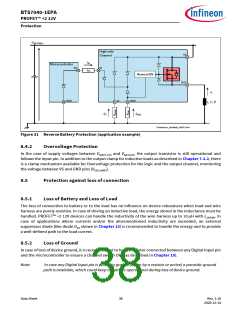
It is possible to “force” a reset of the internal counter without waiting for tDELAY(CR) by applying a pulse (rising
edge followed by a falling edge) to the DEN pin while IN pin is “low”. The pulse applied to DEN pin must have
a duration longer than tDEN(CR) to ensure a reset of the internal counter.
The timings are shown in Figure 30.
IN
t
Short circu it
to ground
t
nRETRY(CR)
nRETRY(CR)
IL
t
In ter nal
counter
0
1
nRETRY(CR)
0
1
nRETRY(CR)
0
t
t
DEN
tDEN(CR)
tDEN(CR)
tDEN(CR)
Protection_PROFET_DENforce_time2.emf
Figure 30 Retry Strategy Timing Diagram with Forced Reset
8.4
Additional protections
8.4.1
Reverse Polarity Protection
In Reverse Polarity condition (also known as Reverse Battery), the output stage is switched ON (see parameter
RDS(REV)) because of ReverseON feature which limits the power dissipation in the output stage. Each ESD diode
of the logic contributes to total power dissipation. The reverse current through the output stage must be
limited by the connected load. The current through Digital Input pins has to be limited as well by an external
resistor (please refer to the Absolute Maximum Ratings listed in Chapter 4.1 and to Application Information in
Chapter 10).
Figure 31 shows a typical application including a device with ReverseON. A current flowing into GND pin (-IGND
)
during Reverse Polarity condition is necessary to activate ReverseON, therefore a resistive path between
module ground and device GND pin must be present.
Data Sheet
37
Rev. 1.10
2020-12-14

 INFINEON [ Infineon ]