BTS7040-1EPA
PROFET™ +2 12V
Diagnosis
9
Diagnosis
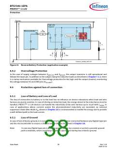
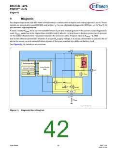
For diagnosis purpose, the BTS7040-1EPA provides a combination of digital and analog signals at pin IS. These
signals are generically named SENSE and written IIS. In case of disabled diagnostic (DEN pin set to “low”), IS
pin becomes high impedance.
A sense resistor RSENSE must be connected between IS pin and module ground if the current sense diagnosis is
used. RSENSE value has to be higher than 820 Ω (or 400 Ω when a central Reverse Battery protection is present
on the battery feed) to limit the power losses in the sense circuitry. A typical value is RSENSE = 1.2 kΩ.
Due to the internal connection between IS pin and VS supply voltage, it is not recommended to connect the IS
pin to the sense current output of other devices, if they are supplied by a different battery feed.
See Figure 32 for details as an overview.
VS
Output Channel
T
Overtemperature
IS Pin Control
Internal Counter
Logic
OUT
IN
DEN
IL / kILIS
To be Updated
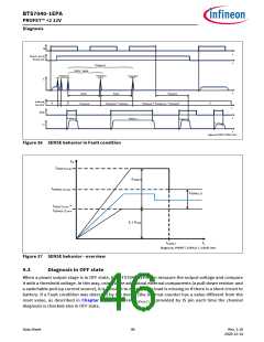
TBD.emf
VDS(OLOFF)
+
IIS(FAULT)
IIS(OLOFF)
MUX
IS
RSENSE
Diag nosis_PROFET_1CH.emf
Figure 32 Diagnosis Block Diagram
Data Sheet
42
Rev. 1.10
2020-12-14

 INFINEON [ Infineon ]