BTS7040-1EPA
PROFET™ +2 12V
Diagnosis
9.1
Overview
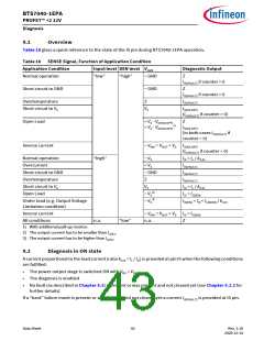
Table 18 gives a quick reference to the state of the IS pin during BTS7040-1EPA operation.
Table 18 SENSE Signal, Function of Application Condition
Application Condition
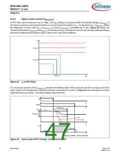
Input level DEN level VOUT
Diagnostic Output
Normal operation
“low”
“high”
~ GND
Z
IIS(FAULT) if counter > 0
Short circuit to GND
~ GND
Z
IIS(FAULT) if counter > 0
Overtemperature
Z
IIS(FAULT)
Short circuit to VS
VS
IIS(OLOFF)
(IIS(FAULT) if counter > 0)
Open Load
< VS - VDS(OLOFF)
> VS - VDS(OLOFF)
Z
1)
IIS(OLOFF)
(in both cases IIS(FAULT) if
counter > 0)
Inverse current
~ VINV = VOUT > VS IIS(OLOFF)
(IIS(FAULT) if counter > 0)
Normal operation
Overcurrent
“high”
~ VS
< VS
~ GND
Z
IIS = IL / kILIS
IIS(FAULT)
Short circuit to GND
Overtemperature
Short circuit to VS
Open Load
IIS(FAULT)
IIS(FAULT)
VS
IIS < IL / kILIS
IIS = IIS(EN)
2)
~ VS
3)
Under load (e.g. Output Voltage
Limitation condition)
~ VS
IIS(EN) < IIS < IL(NOM) / kILIS
Inverse current
~ VINV = VOUT > VS IIS = IIS(EN)
n.a.
All conditions
n.a.
“low”
Z
1) With additional pull-up resistor.
2) The output current has to be smaller than IL(OL)
3) The output current has to be higher than IL(OL)
.
.
9.2
Diagnosis in ON state
A current proportional to the load current (ratio kILIS = IL / IIS) is provided at pin IS when the following conditions
are fulfilled:
•
•
•
The power output stage is switched ON with VDS < VDS(OLOFF)
The diagnosis is enabled
No fault (as described in Chapter 8.3) is present or was present and not cleared yet (see Chapter 9.2.2 for
further details)
If a “hard” failure mode is present or was present and not cleared yet a current IIS(FAULT) is provided at IS pin.
Data Sheet
43
Rev. 1.10
2020-12-14

 INFINEON [ Infineon ]