IDT70V5388/78
3.3V 64/32K x 18 Synchronous FourPort™ Static RAM
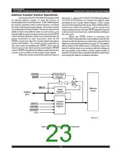
Industrial and Commercial Temperature Ranges
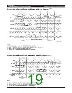
Timing Waveform of Load and Read Address Counter(1,2,3)
t
CYC2
(2)
(3)
t
CH2 tCL2
CLK
tCA2
tSA
tCKHZ
tCKLZ
tHA
(4)
An+2
An
A0
-
A15
tSCLD
tHCLD
CNTLD
CNTINC
tSCINC
tHCINC
tHCRD
tSCRD
CNTRD
INTERNAL
ADDRESS
A
n+1
An+2
A
n
An+2
An+2
,
tDC
tCD2
Qn+2
DATAOUT
Qn+2
Qx
Qn+1
Qn+2
Qx-1
Qn
READ
INTERNAL
ADDRESS
LOAD
EXTERNAL
ADDRESS
READ DATA WITH COUNTER
5649 drw 17
NOTES:
1. CE0, OE, LB and UB = VIL; CE1, R/W, CNTRST, MRST, MKLD and MKRD = VIH.
2. Address in output mode. Host must not be driving address bus after time tCKLZ in next clock cycle.
3. Address in input mode. Host can drive address bus after tCKHZ.
4. This is the value of the address counter being read out on the address lines.
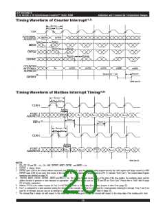
Timing Waveform of Load and Read Mask Register(1,2,3,4)
t
CYC2
t
CH2 CL2
t
(2)
(1)
CLK
tCA2
tSA
tHA
tCKHZ
tCKLZ
(4)
A
n
A0 - A15
An
tSMLD
tHMLD
MKLD
tSMRD
tHMLD
MKRD
MASK
INTERNAL
VALUE
An
A
n
An
An
A
n
An
,
READ
LOAD
MASK-REGISTER
VALUE
MASK REGISTER
VALUE
5649 drw 18
NOTES:
1. Address in output mode. Host must not be driving address bus after time tCKLZ in next clock cycle.
2. Address in input mode. Host can drive address bus after tCKHZ.
3. CE0, OE, LB and UB = VIL; CE1, R/W, CNTRST, MRST, CNTLD, CNTRD and CNTINC = VIH.
4. This is the value of the mask register being read out on the address lines.
19
6.42

 IDT [ INTEGRATED DEVICE TECHNOLOGY ]