ICS1531 Data Sheet - Preliminary
Chapter 7 Programming
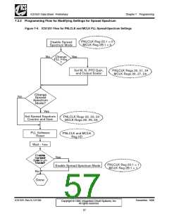
7.3 Programming Spread Spectrum
7.3.1 Spread Spectrum Definition and Purpose
Spread spectrum is a process for distributing (or ‘spreading’) the energy of a single-frequency signal over a
wider frequency spectrum so that it reduces the peak radiated energy on any single frequency.
The need for spread-spectrum technology results from the increase in speeds of PCs and the subsequent
increase in operating resolutions. That is, there has been an increase both in the speed of (1) pixel clocks
for cathode-ray tube displays and (2) panel clocks for LCD displays.
Accompanying these increases has been an increase in generated electro-magnetic interference (EMI). In
some cases, EMI emissions of the fundamental frequency can be too high to pass a country’s
communications regulations [such as those from the American government agency, the Federal
Communications Commission (FCC)].
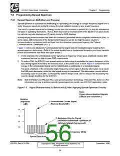
Figure 7-3 shows an idealized (1) unmodulated carrier signal and (2) modulated signal resulting from
spread-spectrum technology. (Both of the actual signals have a fundamental frequency and more variable
peaks and sidebands than what this figure shows.)
1. In this example, the unmodulated carrier signal has a frequency whose peak amplitude creates EMI
emissions that are too high to pass FCC requirements.
2. To reduce EMI, the ICS1531 use spread-spectrum technology to modulate the carrier frequency of the
input timing signals from either the memory clock, or the panel clock, or both. Figure 7-3 shows how the
energy of the unmodulated signal can be redistributed as sidebands of a modulated signal.
The peak amplitude of the composite single-frequency carrier signal is thereby attenuated. As a result,
the EMI peak decreases, while the total signal energy is maintained. This attenuation occurs without
increasing cycle-to-cycle jitter. Consequently, system design costs can be reduced by decreasing the
need to design shielding for the ICS1531.
Note: Both the MCLK and PNLCLK PLLs use spread-spectrum technology. (The pixel PLL does not.) For
information on how to achieve specific spread-spectrum results, see ICS1531 application notes.
Figure 7-3. Signal Characteristics (1) Before and (2) After Applying Spread-Spectrum Circuitry
Note:
Figure shows idealized signals.
(Details are not shown.)
Relative
Amplitude
(dB)
1. Unmodulated Carrier Signal
(Narrow Bandwidth)
0
3
6
9
2. Modulated Carrier Signal
(Increased Bandwidth: Spectrum of
sideband signals has spread.)
Clock Frequency (MHz)
Spread Spectrum
ICS1531 Rev N 12/1/99
December, 1999
Copyright © 1999, Integrated Circuit Systems, Inc.
All rights reserved.
56

 ICSI [ INTEGRATED CIRCUIT SOLUTION INC ]