ICS1531 Data Sheet - Preliminary
Chapter 7 Programming
Chapter 7 Programming
7.1 Industry-Standard 2-Wire Serial Bus: Data Format
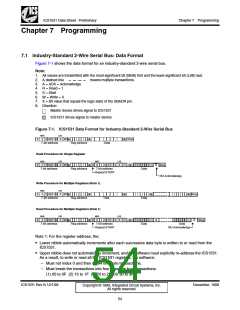
Figure 7-1 shows the data format for an industry-standard 2-wire serial bus.
Note:
1. All values are transmitted with the most-significant bit (MSB) first and the least-significant bit (LSB) last.
2. A dashed line
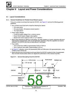
3. A = ACK = Acknowledge
4. R = Read = 1
5. S = Start
means multiple transactions.
6. W = Write = 0
7. X = Bit value that equals the logic state of the SBADR pin.
8. Direction:
Master device drives signal to ICS1531
ICS1531 drives signal to master device
Figure 7-1. ICS1531 Data Format for Industry-Standard 2-Wire Serial Bus
MSB
LSB
S
0
1 0 0 1 0
X
W A
A
A Stop
7-bit address
Reg address
Data
Read Procedure for Single Register
MSB
LSB
MSB
LSB
S
0
1 0 0 1 0
X
W A
A S
0
1
0
0 1
0
X
R
A
A
Stop
7-bit address
Reg address
7-bit address
Repeat START
Data
NO Acknowledge
Write Procedure for Multiple Registers (Note 1)
MSB
LSB
S
0
1 0 0 1 0
X
W A
A
A
R
A
A Stop
7-bit address
Reg address
Data
Data
Data
Read Procedure for Multiple Registers (Note 1)
MSB
LSB
MSB
LSB
S
0
1 0 0 1 0
X
W A
A S
0
1
0
0 1
0
X
A
A
A
Stop
7-bit address
Reg address
7-bit address
Repeat START
Data
NO Acknowledge
Note 1: For the register address, the:
• Lower nibble automatically increments after each successive data byte is written to or read from the
ICS1531.
• Upper nibble does not automatically increment, and the software must explicitly re-address the ICS1531.
As a result, to write or read all the ICS1531 registers, the software:
– Must not index 0 and then do 64 one-byte transactions.
– Must break the transactions into four separate bus transactions:
(1) 00 to 0F (2) 10 to 1F (3) 20 to 2F (4) 30 to 3F
ICS1531 Rev N 12/1/99
December, 1999
Copyright © 1999, Integrated Circuit Systems, Inc.
All rights reserved.
54

 ICSI [ INTEGRATED CIRCUIT SOLUTION INC ]