iC-MR 13-BIT S&H SIN/COS
INTERPOLATOR WITH CONTROLLER INTERFACES
Rev A1, Page 42/44
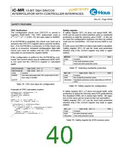
Error bits ERR_EXT, ERR_SYN, ERR_TMP, Register EMASK defines a mask for the ERR bit in the
ERR_AMP and ERR_RGL are stored internally. status byte. If the relevant bit is set in the mask reg-
RES_ERR is used to choose which action resets the ister, the corresponding error bit in the error register is
error bit.
signaled as ERR in the status byte. In the same man-
ner, register WMASK defines a mask for the WARN bit
in the status byte.
RES_ERR
Addr. 0x27; bit 6
Function
R/W
Code
0
1
Reset by readout position data
Reset by readout error register
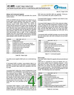
EMASK
Bit
Addr. 0x22; bit 7...0
Message
EM_EXT
EM_ABS
EM_IPO
EM_KNF
EM_SYN
EM_TMP
EM_AMP
EM_RGL
Externally signalized error
Table 83: Error reset
Error in readout of absolute value
Fallen below conversion time of interpolator
Configuration error
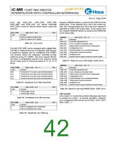
Error bit ERR_AMP can be assigned with a digital filter.
The filter is implemented as an integrator with timeout.
If required a bypass can be configured (EN_FAMP).
The timeout resets the integrator cyclically (config-
urable by using TO_FAMP). The error output’s thresh-
old value is configurable and the error output is being
set at a duty cycle of a timeout period of 17, 34, 51 or
68 µs.
Synchronisation error counter/interpolator
Temperature beyond thresholds
Amplitude error
Beyond control range of transmit current control
Table 87: Mask for error ERR (Addr. 0x60, bit 6)
WMASK
Addr. 0x23; bit 7...0
Message
THR_FAMP
Code
0x0
Addr. 0x2B; bit 3...2
Function
R/W
Bit
WM_EXT
WM_ABS
WM_IPO
WM_KNF
WM_SYN
WM_TMP
Externally signalized error
Threshold at 17 µs duty cycle of timeout period
Threshold at 34 µs duty cycle of timeout period
Threshold at 51 µs duty cycle of timeout period
Threshold at 68 µs duty cycle of timeout period
Error in readout of absolute value
Fallen below conversion time of interpolator
Configuration error
0x1
0x2
0x3
Synchronisation error counter/interpolator
Temperature beyond thresholds
Table 84: Amplitude error filter threshold
WM_AMP Amplitude error
WM_RGL
Beyond control range of transmit current control
TO_FAMP
Addr. 0x2B; bit 1
Function
R/W
Table 88: Mask for warning WARN (Addr. 0x60, bit 5)
Code
0
1
Timeout after 273 µs
Timeout after 546 µs
Life counter
Life counter LC counts the position data generated and
is zeroed on a reset. In normal operation, however,
zero is bypassed and cannot occur (order: 0xFE, 0xFF,
0x01, 0x02 ...).
Table 85: Amplitude error filter timeout
EN_FAMP
Addr. 0x2B; bit 0
Function
R/W
Code
0
1
Filter for amplitude error deactivated
Filter for amplitude error active
Table 86: Amplitude error filtering

 ICHAUS [ IC-HAUS GMBH ]