IBM3009K2672
IBM SONET/SDH Framer
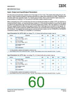
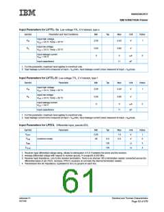
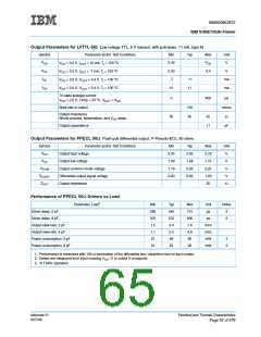
Input Parameters for LVTTL- 5s Low voltage TTL, 5 V tolerant, type s
Symbol
Parameter and Test Conditions
Min
Typ
Max
5.50
Unit
V
Notes
1
Input high voltage
VIH
2.00
V
DD = 3.0 V, Temp = 23 ο
C
Input low voltage
DD = 3.0 V, Temp = 23 ο
VIL
0.00
0
0.80
V
V
C
Input leakage current
VDD = 3.6 V
0
µA
2
Input capacitance
11
pF
1. For this parameter, maximum level applies to overshoot only.
2. Input leakage current (min) measured at Input = VIH(min). Input leakage current (max) measured at Input = VIH(max).
Input Parameters for LVTTL-5f Low voltage TTL, 5 V tolerant, type f
Symbol
Parameter
Min
Typ
Max
5.50
Unit
V
Notes
1
Input high voltage
V
VIH
2.00
DD = 3.0 V, Temp = 23 ο
C
Input low voltage
VIL
0.00
0
0.80
V
V
DD = 3.0 V, Temp = 23 ο
C
Input leakage current
VDD = 3.6 V
0
µA
2
Input capacitance
11
pF
1. For this parameter, maximum level applies to overshoot only.
2. Input leakage current (min) measured at Input = VIH(min). Input leakage current (max) measured at Input = VIH(max).
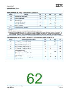
Input Parameters for LPECL Differential input, pseudo-ECL
Symbol
VDIFF
VCM
Parameter
Min
0.25
.95
Typ
Max
1.0
Unit
V
Notes
1
2
3
4
(common mode)
2.0
100
100
2.6
V
ZRIN
Ω
ZTLAC
Ω
1. Receiver input differential voltage swing. Allows for attenuation of 0.6 V between the driver and the receiver.
2. Average differential voltage with respect to receiver ground, V-crosspoint at 200 Mhz.
3. Receiver input impedance. Line to line receiver termination. There is an internal 100 Ω termination resistor connected across the
differential inputs of all LPECL receivers. PPECL receivers do not have the internal termination resistor.
4. Transmission line AC impedance. Equivalent to 50 Ω to ground on each line.
ssframer.01
8/27/99
Electrical and Thermal Characteristics
Page 53 of 279

 IBM [ IBM ]