IBM3009K2672
IBM SONET/SDH Framer
Outgoing Pointer Adjustment events and NDF events are counted in 8-bit counters. Pointer processing is per-
formed per [G.783], [G.707], and [GR-253]. AU-4 Pointer adjustments, NDF events, and pointer defect events
are counted in 8-bit counters. Optional transmit pointer retiming can be enabled for transmit Telecom Bus,
ATM, or PPP applications. For ATM/PPP applications, the AU-4 pointer offset can be fixed to ‘0’.
Note: No processing is performed on the receive TOH bytes that are reserved for national use or interna-
tional standardization.
APS Functions
An integrated cross connect is provided for APS applications. For single device operation, 1:3 multiplex sec-
tion trail protection can be achieved. If a multi-device configuration is implemented, a 1:N (N can range from 1
up to 14) multiplex section trail protection can be realized through the external bidirectional APS interface
(see RACC and TACC - Receive/Transmit APS Cross Connect on page 9). Three maskable interrupt request
bits are provided for indicating to the external microprocessor that a potential bridge, switch, or switch release
is being requested and that the receive K1 and K2 bytes need to be read and interpreted. Based on the
receive K1 and K2 bytes, the APSSELECT bits in the HT1Conf14 register and the ApsSource bits in the
HR1Conf11 register can be written with the appropriate code to cause a bridge to the protection channel or
switch to the protection channel as desired. A control bit (Pchan) is provided in each macro to enable a partic-
ular channel as the protection channel in order to cause the K1 bytes of the working channels to be ignored.
An 8-bit counter is provided for counting parity errors that are detected on the APS bus.
Transmit/Receive Higher-Order Path Connection Function Layer Options
The SONET/SDH framer has the ability to fold back a receive VC-4 from any of the four SFH Macros and
assign them to any transmit VC-4 via software control. For instance, the receive VC-4 from STM-1 #1 can be
folded back and applied to transmit VC-4 of STM-1 #3. In short, only the logical order of the VC-4 is changed.
The higher-order path connection function can also be performed under software control at the TCS Function
(TCSF) where only the C-4 s are folded back. This applies only to ATM-PPP mode.
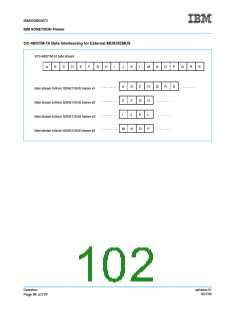
OC-48/STM-16 Expansion Port
The SONET/SDH framer can be combined with three other SONET/SDH framers to form an STS-48 or STM-
16 signal that consists of either 4 x STM-4, 4 x STM-4c, 4 x STS-12, or 4 x STS-12c. The parallel line inter-
faces are used in this application. A MUX/DEMUX device that performs clock recovery and synthesis is
needed to interface the OC-48 or STM-16 serial stream to the SONET/SDH framers. The FP1 pulse in the
receive direction should be aligned to the first SPE/VC-4 byte in the first row of the SONET/SDH frame.
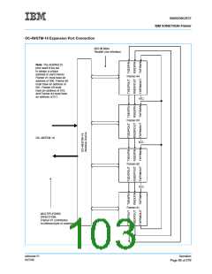
The OC-48/STM-16 expansion port is used to provide inter-SONET/SDH framer communication of B1 infor-
mation, received B2 errors, and AIS indications. That is, a B1 calculation is performed across the data of all
four SONET/SDH framers. B2 errors are summed up from all four SONET/SDH framers and put into the M1
byte. The detection of Line AIS as detected by the K2 byte in the first SONET/SDH framer is also indicated to
the other three SONET/SDH framers. Additionally, the OC-48/STM-16 expansion port synchronizes the
SONET/SDH framers together so that scrambling/descrambling can be performed by the SONET/SDH fram-
ers. The MUX/DEMUX needs to MUX/DEMUX the data between the OC-48 stream and the four
SONET/SDH framers four bytes at a time, as shown in the following figure.
ssframer.01
8/27/99
Operation
Page 93 of 279

 IBM [ IBM ]