IBM3009K2672
IBM SONET/SDH Framer
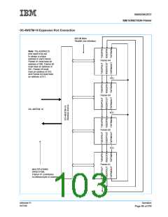
OC-48/STM-16 Expansion Port Connection on page 95 shows four SONET/SDH framers connected for OC-
48/STM-16 operation via their expansion ports. See OC-48 Expansion Port Timing on page 66 for notes on
timing considerations. The ADDR(2:0) pins of each SONET/SDH framer need to be set to identify which
SONET/SDH framer is number 1, which is 2, which is 3, and which is 4. The OC-48/STM-16 device provides
multiplexing, parallel-to-serial conversion, and clock synthesis in the transmit direction, and performs clock
recovery, byte alignment, and serial-to-parallel conversion in the receive direction. The byte-parallel inter-
faces of the SONET/SDH framer are used to interface to the OC-48/STM-16 Interface Device. The line side
of each SONET/SDH framer can be individually configured to process STM-4, STM-4c, STS-12, or STS-12c
frames. The terminal side of each SONET/SDH framer can be individually programmed to support Telecom
Bus, UTOPIA Level 2+ (PPP over SONET/SDH), UTOPIA Level 2, or dual UTOPIA Level 1 interfaces).
Ring Port
The ring port is used to communicate between K1, K2, K3, Path RDI, Line RDI, Path FEBE, Line FEBE, and
the alarms associated with the K1, K2, and K3 bytes.
The ring port is a serial interface that is used to exchange various SONET/SDH-specific alarm, bit or block
error information, and APS information, among SONET/SDH framers when operating in a counter-rotating
unidirectional ring network. Thus, the ring port replaces the SONET/SDH framer internal remote alarm,
bit/block error, and APS signaling which is used in bidirectional point-to-point SONET/SDH applications when
the RING control bit is set to ‘1’. In other words, when RING is set to ‘1’, path and line RDI and FEBE are not
inserted into the local transmit SDH stream. Instead they are passed to a mating SONET/SDH framer via the
ring port along with APS information. The mating SONET/SDH framer will then transmit the line or path FEBE
or RDI. When RING is set to ’0’, the ring port is not used at all and the local SONET/SDH framer will generate
line or path RDI as appropriate.
Note: When the SONET/SDH framer is operating in Telecom Bus mode, all of the transmit POH information
output to the line will be derived from the transmit Telecom Bus inputs and not from the ring port regardless of
the setting of the RING bit. This feature will allow a POH Processor to perform POH processing while the
SONET/SDH framer processes TOH.
The functions of the ring port are indicated in the subsections below.
The RXRINGD and RXRINGCLK signals connect directly to their corresponding TXRINGD and TXRINGCLK
pins on a mating SONET/SDH framer. The RXRINGCLK clock is 19.44 MHz 20 ppm and is derived from the
transmit Line Reference Clock of the SONET/SDH framer that is driving that signal.
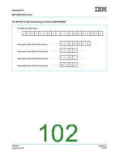
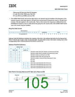
The format of the ring port data that is output on the RXRINGD pin is shown in Ring Port Data Format on
page 97. The leftmost bit is transmitted first. The information consists of twenty 29-bit fields, one for each of
the K1, K2, and K3 bytes, and Line and Path FEBE values, plus their associated alarms, for all four STM-
1/STS-3c signals. The sub-fields of the RXRINGD signal are:
• A 15-bit start sequence consisting of 14 consecutive ‘0’s followed by a ‘1’ (i.e., 0000 0000 0000 001). This
field is used by the mating SONET/SDH framer to determine the location of the address and data fields.
• A 5-bit address field. This field identifies to the mating SONET/SDH framer what the contents of the 9-bit
data field are and from which STM-1/STS-3c it came. When an STM-4c or STS-12c is processed, the
section number field will be set to ’0’ since there is only one set of POH to process. Also note that when
an STM-4 or STS-12 is processed, the section number field will indicate with which VC-4 (1-4) the ring
port data is associated.
• A 9-bit data field. This field will contain one of the following:
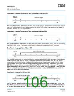
- Debounced K1 byte plus a reserved bit.
- Debounced K2 byte plus New APS indication.
Operation
ssframer.01
8/27/99
Page 96 of 279

 IBM [ IBM ]