RFM70 V1.0
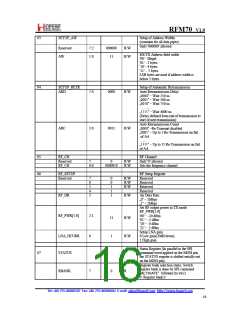
Setup of Address Widths
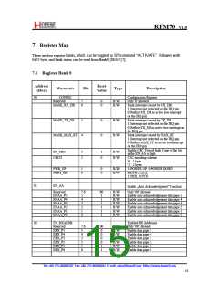
03
SETUP_AW
(common for all data pipes)
Only '000000' allowed
Reserved
AW
7:2
1:0
000000
11
R/W
R/W
RX/TX Address field width
'00' - Illegal
'01' - 3 bytes
'10' - 4 bytes
'11' - 5 bytes
LSB bytes are used if address width is
below 5 bytes
04
SETUP_RETR
ARD
Setup of Automatic Retransmission
Auto Retransmission Delay
„0000‟ – Wait 250 us
7:4
0000
R/W
„0001‟ – Wait 500 us
„0010‟. – Wait 750 us
…….
„1111‟ – Wait 4000 us
(Delay defined from end of transmission to
start of next transmission)
Auto Retransmission Count
„0000‟ –Re-Transmit disabled
„0001‟ – Up to 1 Re-Transmission on fail
of AA
ARC
3:0
0011
R/W
……
„1111‟ – Up to 15 Re-Transmission on fail
of AA
05
06
RF_CH
Reserved
RF_CH
RF Channel
Only '0' allowed
Sets the frequency channel
7
6:0
0
R/W
R/W
0000010
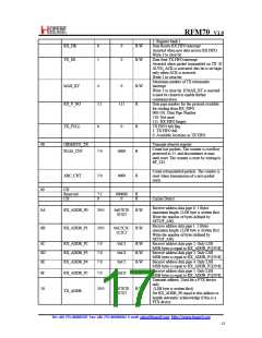
RF_SETUP
Reserved
RF Setup Register
Reserved
Reserved
Reserved
Reserved
7
6
5
4
3
0
0
1
1
1
R/W
R/W
R/W
RF_DR
R/W
Air Data Rate
„0‟ – 1Mbps
„1‟ – 2Mbps
Set RF output power in TX mode
RF_PWR[1:0]
'00' – -10 dBm
'01' – -5 dBm
'10' – 0 dBm
RF_PWR[1:0]
2:1
0
11
1
R/W
R/W
'11' – 5 dBm
Setup LNA gain
0:Low gain(20dB down)
1:High gain
LNA_HCURR
STATUS
Status Register (In parallel to the SPI
command word applied on the MOSI pin,
the STATUS register is shifted serially out
on the MISO pin)
07
Register bank selection states. Switch
register bank is done by SPI0command
RBANK
7
0
R
“ACTIVATE” followed by
x53
0: Register bank 0
Tel: +86‐755‐86096587 Fax: +86‐755‐86096602 E‐mail: sales@hoperf.com http://www.hoperf.com
16

 HOPERF [ HOPERF ]