RFM68CW
RFM68CW
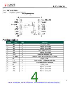
4. Application Modes of the RFM68CW
Pins CTRL and DATA are used for both configuring the circuit and sending the data to be transmitted over the air. Two
different modes are associated to these pins, “Power&Go” and “Advanced” modes.
4.1. Transmitter Modes
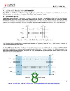
Automatic Mode operation is described in Figure 2. Here we see that a rising edge on the DATA pin activates the
transmitter start-up process. DATA must be held high for the start-up time (TS_TR) of the RFM68CW. During this time the
RFM68CW undergoes an optimized, self-calibrating trajectory from Sleep mode to Transmit mode. Once this time has
elapsed, the RFM68CW is ready to transmit. Any logical signal subsequently applied to the DATA pin is then transmitted.
Figure 2.
‘Power & Go’ Mode: Transmitter Timing Operation
The transition back to Sleep mode is managed automatically. The RFM68CW waits for TOFFT (2 or 20 ms) of inactivity on
DATA before returning to Sleep mode.
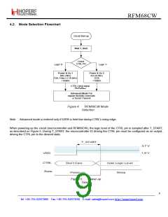
In Forced Transmit Mode the circuit can be forced to wake up and go to TX mode by sending an APPLICATION
instruction through the TWI interface, and setting the Mode bit DA(15) to ‘1’. Once in Transmit the circuit will transmit over
the air the data stream presented on the DATA pin. The circuit will stay in transmit mode until a new APPLICATION
instruction is sent with DA(15) to ‘0’.
Figure 3.
Forced Transmit Mode
Description
8
Tel: +86-755-82973805 Fax: +86-755-82973550 E-mail: sales@hoperf.com http://www.hoperf.com

 HOPERF [ HOPERF ]