RFM68CW
RFM68CW
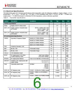
Symbol
Description
Conditions
Min
Typ
Max
Unit
For 315MHz Module
For 433,868,915MHz Module
Crystal Oscillator Frequency
24
26
FXOSC
MHz
MHz
DFXOSC
Frequency Variation of the XOSC
No crystal contribution
-
-
+/-25 ppm
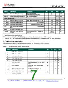
Timing Specifications
TS_TR
Time from Sleep to Tx mode
XTAL dependant, with spec’d XTAL
315 to 390 MHz
-
-
-
650
250
200
2000 us
TS_HOP0 Channel hop time in Band 0
TS_HOP1 Channel hop time in Band 1
500
400
us
us
Maximum hop of 26 MHz***
Programmable
TOFFT
Timer from Tx data activity to
Sleep
-
-
2
20
-
-
ms
ms
RAMP
PA Ramp up and down time
-
-
20
-
-
us
T_START
Time before CTRL pin mode
selection.
Time from power on to sampling of
CTRL **
200 us
+ TS_OSC
ms
*
With different matching networks
** The oscillator startup time, TS_OSC, depends on the electrical characteristics of the crystal
*** From the last CTRL falling edge of the Frequency change instruction to transmitter ready (PA ramp up finished)
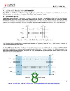
3. Timing Characteristics
The following table gives the operating specifications for the TWI interface of the RFM68CW.
Table 5 Serial Interface Timing Specifications
Symbol Description
Conditions
Min
-
Typ
Max
Unit
MHz
ns
f
t
t
t
t
t
CTRL Clock Frequency
CTRL Clock High time
CTRL Clock Low time
CTRL Clock rise time
CTRL Clock Fall time
-
-
-
-
-
-
10
-
CTRL
ch
45
45
-
-
ns
cl
5
5
-
ns
rise
fall
-
ns
From Data transition to CTRL rising
edge
45
ns
setup
DATA Setup time
DATA hold time
t
From CTRL rising edge to DATA
transition
45
-
-
-
-
-
5
-
ns
us
us
hold
t0, t
Time at “1” on DATA during
Recovery command
See Figure 9 and Figure 10
2
t
Time at “0” on DATA during
Recovery command
See Figure 10
5
1
7
Tel: +86-755-82973805 Fax: +86-755-82973550 E-mail: sales@hoperf.com http://www.hoperf.com

 HOPERF [ HOPERF ]