RFM68CW
RFM68CW
4.3. Application Mode: Power &Go
The default ‘Power & Go’ application mode sees the RFM68CW configured as detailed in Table 6. By changing the logical
state of the CTRL pin at Power-up or Reset, two distinct configuration modes can be selected. The Power & Go application
modes hence permit microcontroller-less operation.
Table 6 Configuration in Power & Go Mode
CTRL Pin
‘Low’
Configuration
Mode
FSK 868.3 MHz, +10 dBm, Fdev=+/-19.2 kHz
Power&Go 1
Power&Go 2
‘High’
OOK 433.92 MHz, +10 dBm
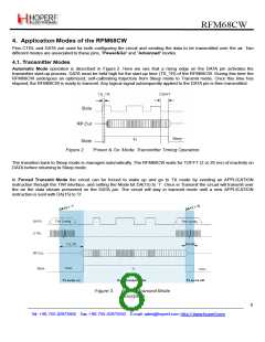
4.4. Application Mode: Advanced
4.4.1. Advanced Mode: Configuration
As described on Figure 4, Advanced mode is entered when accessing the Two Wire Interface (TWI) bus of the RFM68CW.
Upon communication to the register at up to 10 MHz of clocking speed, complete flexibility on the use of the module is
obtained.
Once all register settings are selected (see registers detailed description in section [5]), the RFM68CW can be used either
in
Automatic mode by simply toggling the DATA pin, or in Forced Transmit mode to optimize timings for instance.
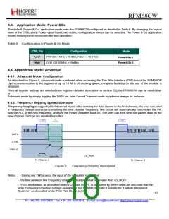
4.4.2. Frequency Hopping Spread Spectrum
Frequency hopping is supported in Advanced mode. After sending the data stream in the first channel, the user can send
a Frequency change instruction containing the new channel frequency. The circuit will automatically ramp down the PA,
lock the PLL to the new frequency, and turn the Power Amplifier back on. The user can then send his packet data on the
new channel. Timings are detailed hereafter:
t < TOFFT
TWI
t < TOFFT
(2 or 20 ms)
instruction
(2 or 20 ms)
Frequencychange
Frequencychange
DATA
CTRL
RFOUT
5th falling
edge on CTRL
24th falling
edge on CTRL
TS_HOPi
Tx Channel
A
Tx Channel
B
Figure 6.
Frequency Hopping Description
Notes
- During any TWI access, the input of the modulator is inhibited
- The time between two Frequency change instructions shall be greater than TS_HOPi
- FHSS modulation, as described under FCC part 15.247, is supported by the RFM68CW; also note that the
large Frequency Deviation settings available on the RFM68CW make it suitable for “Digitally Modulated
Systems”, as described under FCC Part 15.247 (a)(2)
10
Tel: +86-755-82973805 Fax: +86-755-82973550 E-mail: sales@hoperf.com http://www.hoperf.com

 HOPERF [ HOPERF ]