RFM68CW
RFM68CW
5. RFM68CW Configuration
The RFM68CW has several configuration parameters which can be selected through the serial
interface
5.1. TWI Access
As long as CTRL is kept stable, the DATA pin is considered by the circuit as the input for the data to be transmitted over the
air (Power&Go modes).
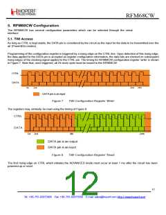
Programming of the configuration register is triggered by a rising edge on the CTRL line. Upon detection of this rising edge,
the data applied to the DATA pin is accepted as register configuration information, the data bits are clocked on subsequent
rising edges of the clocking signal applied to the CTRL pin. The timing for RFM68CW configuration register ‘write’ is shown
in Figure 7. Note that, once triggered, all 24 clock cycle must be issued to the RFM68CW.
CTRL
DATA
1st
2nd
23rd
24th
DATA pin is an input
Figure 7.
TWI Configuration Register ‘Write’.
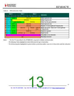
The registers may, similarly, be read using the timing of Figure 8.
CTRL
DATA
1st 2nd
8th
24th
DATA pin is an output
DATA pin is an input
Figure 8.
TWI Configuration Register ‘Read’.
The first rising edge on CTRL which initiates the ADVANCED mode must occur at least 1 ms after the circuit has been
powered up or reset.
12
Tel: +86-755-82973805 Fax: +86-755-82973550 E-mail: sales@hoperf.com http://www.hoperf.com

 HOPERF [ HOPERF ]