RFM68CW
RFM68CW
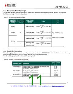
4.5. Frequency Band Coverage
The RFM68CW offers several combinations or frequency references and frequency outputs, allowing for maximum
flexibility and design of multi-band products:
Table 7 Frequency Selection Table
Reference
Frequency
FXOSC
Upper / Lower
Frequency
Bounds
Band Setting
DA(13)
Frf &
Fdev
Fstep
22x106
-----------------
214
Fstep=
Fstep=
= 1.34277kHz
= 1.46484kHz
22 MHz
24 MHz
310 to 450 MHz
312 to 450 MHz
338 to 450 MHz
24x106
-----------------
0
214
Frf= DF(18;0) × Fstep
Fdev= DA(12;5) × Fstep
26x106
-----------------
Fstep=
Fstep=
= 1.58691kHz
214
26 MHz
6
860 to 870 MHz
and
902 to 928 MHz
26x10
-----------------
213
= 3.17383kHz
1
4.6. Power Consumption
The following typical power consumption figures are observed on the RFM68CW kits. Note that the transmitter efficiency
depends on the impedance matching quality, and can be PCB design dependant.
The PA matching may be different in each frequency band.
Table 8 Power Consumption in Tx mode
Typical Current
Frequency Band
Conditions
Drain
310 to 450 MHz
Pout=+10dBm, OOK modulation with 50% duty cycle
Pout=+10dBm, FSK modulation
Pout=0dBm, FSK modulation
11 mA
15 mA
9 mA
860 to 870 MHz
902 to 928 MHz
Pout=+10dBm, FSK modulation
Pout=0dBm, FSK modulation
16.5 mA
10 mA
Pout=+10dBm, FSK modulation
Pout=0dBm, FSK modulation
17.5 mA
10.5 mA
11
Tel: +86-755-82973805 Fax: +86-755-82973550 E-mail: sales@hoperf.com http://www.hoperf.com

 HOPERF [ HOPERF ]