RFM68CW
RFM68CW
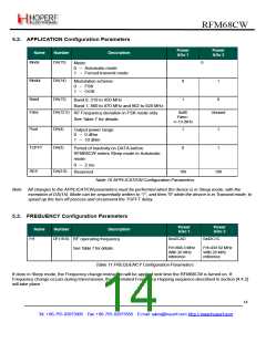
5.2. APPLICATION Configuration Parameters
Power
&Go 1
Power
&Go 2
Name
Mode
Number
Description
DA(15)
0
Mode:
0 → Automatic mode
1 → Forced transmit mode
Modul
DA(14)
0
1
1
Modulation scheme:
0 → FSK
1 → OOK
Band
Fdev
DA(13)
0
Band 0, 310 to 450 MHz
Band 1, 860 to 870 MHz and 902 to 928 MHz
DA(12:5)
0x06
Fdev=
+/-19.2kHz
Unused
RF Frequency deviation in FSK mode only
See Table 7 for details
Pout
DA(4)
DA(3)
1
1
1
Output power range:
0 → 0 dBm
1 → 10 dBm
TOFFT
0
Period of inactivity on DATA before
RFM68CW enters Sleep mode in Automatic
mode:
0 → 2 ms
RES
DA(2:0)
100
100
Reserved
Table 10 APPLICATION Configuration Parameters
Note All changes to the APPLICATION parameters must be performed when the device is in Sleep mode, with the
exception of DA(15). Mode can be sequentially written to “1”, and then “0” while the device is in Transmit mode, to
speed up the turn off process and circumvent the TOFFT delay.
5.3. FREQUENCY Configuration Parameters
Power
&Go 1
Power
&Go 2
Name
Frf
Number
Description
DF(18:0)
0x42CAD
0x42C1C
RF operating frequency
Frf=868.3 MHz
With 26 MHz
reference
Frf=433.92 MHz
With 26 MHz
reference
See Table 7 for details
Table 11 FREQUENCY Configuration Parameters
If done in Sleep mode, the Frequency change instruction will be applied next time the RFM68CW is turned on. If
Frequency change occurs during transmission, the automated Frequency Hopping sequence described in section [4.4.2]
will take place.
14
Tel: +86-755-82973805 Fax: +86-755-82973550 E-mail: sales@hoperf.com http://www.hoperf.com

 HOPERF [ HOPERF ]