HT46R01A
Interrupt Register
tine, to allow interrupt nesting. If the stack is full, the in-
terrupt request will not be acknowledged, even if the
related interrupt is enabled, until the Stack Pointer is
decremented. If immediate service is desired, the stack
must be prevented from becoming full.
Overall interrupt control, which means interrupt enabling
and request flag setting, is controlled by a single INTC0
register, which is located in the Data Memory. By con-
trolling the appropriate enable bits in these registers
each individual interrupt can be enabled or disabled.
Also when an interrupt occurs, the corresponding re-
quest flag will be set by the microcontroller. The global
enable flag if cleared to zero will disable all interrupts.
Interrupt Priority
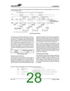
Interrupts, occurring in the interval between the rising
edges of two consecutive T2 pulses, will be serviced on
the latter of the two T2 pulses, if the corresponding inter-
rupts are enabled. In case of simultaneous requests, the
following table shows the priority that is applied. These
can be masked by resetting the EMI bit.
Interrupt Operation
A Timer/Event Counter overflow, an end of A/D conver-
sion or an active edge on the external interrupt pin will all
generate an interrupt request by setting their corre-
sponding request flag, if their appropriate interrupt en-
able bit is set. When this happens, the Program
Counter, which stores the address of the next instruction
to be executed, will be transferred onto the stack. The
Program Counter will then be loaded with a new ad-
dress which will be the value of the corresponding inter-
rupt vector. The microcontroller will then fetch its next
instruction from this interrupt vector. The instruction at
this vector will usually be a JMP statement which will
jump to another section of program which is known as
the interrupt service routine. Here is located the code to
control the appropriate interrupt. The interrupt service
routine must be terminated with a RETI statement,
which retrieves the original Program Counter address
from the stack and allows the microcontroller to continue
with normal execution at the point where the interrupt
occurred.
Interrupt Source
External Interrupt
HT46R01A
1
2
3
Timer/Event Counter 0 Overflow
A/D Converter Interrupt
In cases where both external and internal interrupts are
enabled and where an external and internal interrupt oc-
curs simultaneously, the external interrupt will always
have priority and will therefore be serviced first. Suitable
masking of the individual interrupts using the interrupt
registers can prevent simultaneous occurrences.
External Interrupt
For an external interrupt to occur, the global interrupt en-
able bit, EEI, and external interrupt enable bit, EEI, must
first be set. An actual external interrupt will take place
when the external interrupt request flag, EIF, is set, a sit-
uation that will occur when an edge transition appears
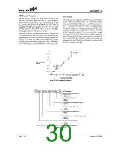
on the external INTline. The type of transition that will
trigger an external interrupt, whether high to low, low to
high or both is determined by the INTES0 and INTES1
bits, which are bits 6 and 7 respectively, in the CTRL1
control register. These two bits can also disable the ex-
ternal interrupt function.
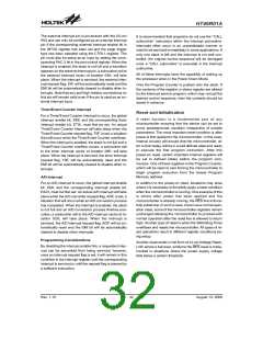
The various interrupt enable bits, together with their as-
sociated request flags, are shown in the following dia-
gram with their order of priority.
Once an interrupt subroutine is serviced, all the other in-
terrupts will be blocked, as the EMI bit will be cleared au-
tomatically. This will prevent any further interrupt nesting
from occurring. However, if other interrupt requests oc-
cur during this interval, although the interrupt will not be
immediately serviced, the request flag will still be re-
corded. If an interrupt requires immediate servicing
while the program is already in another interrupt service
routine, the EMI bit should be set after entering the rou-
INTES1
INTES0
Edge Trigger Type
Disable
0
0
1
1
0
1
0
1
Rising Edge Trigger
Falling Edge Trigger
Dual Edge Trigger
A
u
t
o
m
a
t
i
c
a
l
l
y
C
l
e
a
r
e
d
b
y
I
S
R
A
u
t
o
m
a
t
i
c
a
l
l
y
D
i
s
a
b
l
e
d
b
y
I
S
R
M
a
n
u
a
l
l
y
S
e
t
o
r
C
l
e
a
r
e
d
b
y
S
o
f
t
w
a
r
e
C
a
n
b
e
E
n
a
b
l
e
d
M
a
n
u
a
l
l
y
P
r
i
o
r
i
t
y
E
x
t
e
r
n
a
l
I
n
t
e
r
r
u
p
t
E
E
E
T
I
E
M
I
H
i
g
h
R
e
q
u
e
s
t
F
l
a
g
E
I
F
T
i
m
e
r
/
E
v
e
n
t
C
o
u
n
t
e
r
0
I
n
t
e
r
r
u
p
t
0
I
I
n
t
e
r
r
u
p
t
R
e
q
u
e
s
t
F
l
a
g
T
0
F
P
o
l
l
i
n
g
A
/
D
C
o
n
v
e
r
t
e
r
E
A
D
I
I
n
t
e
r
r
u
p
t
R
e
q
u
e
s
t
F
l
a
g
A
D
F
L
o
w
Interrupt Scheme
Rev. 1.10
31
August 13, 2008

 HOLTIC [ HOLT INTEGRATED CIRCUITS ]