HT46R01A
Programming Considerations
the timer registers before the timer is switched on; this is
because after power-on the initial values of the timer reg-
isters are unknown. After the timer has been initialised
the timer can be turned on and off by controlling the en-
able bit in the timer control register.
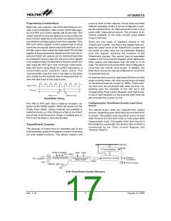
When configured to run in the timer mode, the internal
system clock is used as the timer clock source and is
therefore synchronised with the overall operation of the
microcontroller. In this mode when the appropriate timer
register is full, the microcontroller will generate an internal
interrupt signal directing the program flow to the respec-
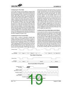
tive internal interrupt vector. For the pulse width mea-
surement mode, the internal system clock is also used as
the timer clock source but the timer will only run when the
correct logic condition appears on the external timer input
pin. As this is an external event and not synchronised
with the internal timer clock, the microcontroller will only
see this external event when the next timer clock pulse
arrives. As a result, there may be small differences in
measured values requiring programmers to take this into
account during programming. The same applies if the
timer is configured to be in the event counting mode,
which again is an external event and not synchronised
with the internal system or timer clock.
When the Timer/Event Counter overflows, its corre-
sponding interrupt request flag in the interrupt control
register will be set. If the timer interrupt is enabled this
will in turn generate an interrupt signal. However irre-
spective of whether the interrupts are enabled or not, a
Timer/Event counter overflow will also generate a
wake-up signal if the device is in a Power-down condi-
tion. This situation may occur if the Timer/Event Counter
is in the Event Counting Mode and if the external signal
continues to change state. In such a case, the
Timer/Event Counter will continue to count these exter-
nal events and if an overflow occurs the device will be
woken up from its Power-down condition. To prevent
such a wake-up from occurring, the timer interrupt re-
quest flag should first be set high before issuing the
²HALT² instruction to enter the Power Down Mode.
When the Timer/Event Counter is read, or if data is writ-
ten to the preload register, the clock is inhibited to avoid
errors, however as this may result in a counting error, this
should be taken into account by the programmer. Care
must be taken to ensure that the timers are properly in-
itialised before using them for the first time. The associ-
ated timer enable bits in the interrupt control register must
be properly set otherwise the internal interrupt associated
with the timer will remain inactive. The edge select, timer
mode and clock source control bits in timer control regis-
ter must also be correctly set to ensure the timer is prop-
erly configured for the required application. It is also
important to ensure that an initial value is first loaded into
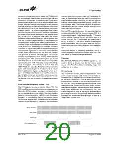
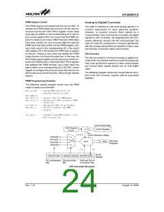
Timer Program Example
The program shows how the Timer/Event Counter regis-
ters are setup along with how the interrupts are enabled
and managed. Note how the Timer/Event Counter is
turned on, by setting bit 4 of the Timer Control Register.
The Timer/Event Counter can be turned off in a similar
way by clearing the same bit. This example program
sets the Timer/Event Counters to be in the timer mode,
which uses the internal system clock as their clock
source.
:
org 04h
:
; external interrupt vector
org 08h
jmp tmr0int
; Timer Counter 0 interrupt vector
; jump here when Timer 0 overflows
:
:
org 20h
:
; main program
:
;internal Timer 0 interrupt routine
tmr0int:
:
; Timer 0 main program placed here
:
:
begin:
;setup Timer 0 registers
mov a,09bh
tmr0,a
; setup Timer 0 preload value
mov a,081h ; setup Timer 0 control register
mov tmr0c,a ; timer mode and prescaler set to /2
;setup interrupt register
mov a,00dh
; interrupts
intc0,a
:
; enable master interrupt and both timer
:
set tmr0c.4
:
; start Timer 0
:
Rev. 1.10
21
August 13, 2008

 HOLTIC [ HOLT INTEGRATED CIRCUITS ]