HT46R01A
Configuring the Timer Mode
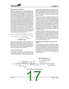
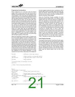
will increment each time the external timer pin receives
a high to low transition. As in the case of the other two
modes, when the counter is full, the timer will overflow
and generate an internal interrupt signal. The counter
will then preload the value already loaded into the
preload register. As the external timer pins are
pin-shared with other I/O pins, to ensure that the pin is
configured to operate as an event counter input pin, two
things have to happen. The first is to ensure that the
T0M1/T0M0 bits place the Timer/Event Counter in the
event counting mode, the second is to ensure that the
port control register configures the pin as an input. It
should be noted that a timer overflow is one of the inter-
rupt and wake-up sources. Note that the timer interrupts
can be disabled by ensuring that the ET0I bits in the
INTC0 register are reset to zero.
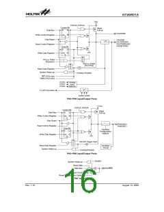
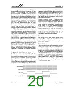
In this mode, the timer can be utilized to measure fixed
time intervals, providing an internal interrupt signal each
time the counter overflows. To operate in this mode, the
bit pair, T0M1/T0M0, must be set to 1 and 0 respectively.
In this mode the internal clock is used as the timer clock.
The timer input clock source is either fSYS or the RTC os-
cillator. However, this timer clock source is further di-
vided by a prescaler, the value of which is determined by
the bits T0PSC2~T0PSC0 in the Timer Control Regis-
ter. The timer-on bit, T0ON must be set high to enable
the timer to run. Each time an internal clock high to low
transition occurs, the timer increments by one; when the
timer is full and overflows, an interrupt signal is gener-
ated and the timer will preload the value already loaded
into the preload register and continue counting. A timer
overflow condition and corresponding internal interrupt
is one of the wake-up sources, however, the internal in-
terrupts can be disabled by ensuring that the ET0I bits of
the INTC0 register are reset to zero.
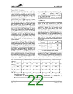
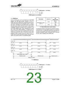
Configuring the Pulse Width Measurement Mode
In this mode, the width of external pulses applied to the
external timer pin can be measured. In the Pulse Width
Measurement Mode the timer clock source is supplied
by the internal clock. For the timer to operate in this
mode, the bit pair, T0M1/T0M0 must both be set high. If
the T0E bit is low, once a high to low transition has been
received on the external timer pin, the timer will start
counting until the external timer pin returns to its original
high level. At this point the T0ON bit will be automatically
reset to zero and the timer will stop counting. If the T0E
bit is high, the timer will begin counting once a low to
high transition has been received on the external timer
pin and stop counting when the external timer pin re-
Configuring the Event Counter Mode
In this mode, a number of externally changing logic
events, occurring on the external timer pin, can be re-
corded by the internal timer. For the timer to operate in
the event counting mode, the bit pair, T0M1/T0M0 must
be set to 0 and 1 respectively. The timer-on bit T0ON or
T1ON, depending upon which timer is used, must be set
high to enable the timer to count. If T0E is low, the coun-
ter will increment each time the external timer pin re-
ceives a low to high transition. If T0E is high, the counter
P
r
e
s
c
a
l
e
r
O
u
t
p
u
t
I
n
c
r
e
m
e
n
t
T
i
m
e
r
+
2
T
i
m
e
r
+
N
T
i
m
e
r
+
N
+
1
T
i
m
e
r
+
1
T
i
m
e
r
C
o
n
t
r
o
l
l
e
r
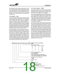
Timer Mode Timing Chart
E
x
t
e
r
n
a
l
E
v
e
n
t
I
n
c
r
e
m
e
n
t
T
i
m
e
r
+
1
T
i
m
e
r
+
2
T
i
m
e
r
+
3
T
i
m
e
r
C
o
u
n
t
e
r
Event Counter Mode Timing Chart
E
x
t
e
r
n
a
l
T
i
m
e
r
P
i
n
I
n
p
u
t
T
0
O
N
o
r
T
1
O
N
(
w
i
t
h
T
0
E
o
r
T
1
E
=
0
)
P
r
e
s
c
a
l
e
r
O
u
t
p
u
t
I
n
r
c
r
e
m
e
n
t
+
1
+
2
+
3
+
4
T
u
i
m
e
r
T
i
m
e
C
o
u
n
t
e
r
P
r
e
s
c
a
l
e
r
O
u
t
p
t
i
s
s
a
m
p
l
e
d
a
t
e
v
e
r
y
f
a
l
l
i
n
g
e
d
g
e
o
f
T
1
.
Pulse Width Measure Mode Timing Chart
Rev. 1.10
19
August 13, 2008

 HOLTIC [ HOLT INTEGRATED CIRCUITS ]