HT46R01A
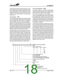
Timer Control Registers - TMR0C
The flexible features of the Holtek microcontroller
Timer/Event Counters enable them to operate in three
different modes, the options of which are determined by
the contents of their respective control register.
An external clock source is used when the timer is in the
event counting mode, the clock source being provided
on an external timer pin TMR0, depending upon which
device and which timer is used. Depending upon the
condition of the T0E bit, each high to low, or low to high
transition on the external timer pin will increment the
counter by one.
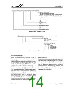
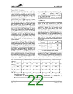
The Timer Control Register is known as TMR0C. It is the
Timer Control Register together with its corresponding
timer registers that control the full operation of the
Timer/Event Counters. Before the timers can be used, it
is essential that the appropriate Timer Control Register
is fully programmed with the right data to ensure its cor-
rect operation, a process that is normally carried out
during program initialisation.
Timer Registers - TMR0
The timer registers are special function registers located
in the Special Purpose Data Memory and is the place
where the actual timer value is stored. This register is
known as TMR0. The value in the timer registers in-
creases by one each time an internal clock pulse is re-
ceived or an external transition occurs on the external
timer pin. The timer will count from the initial value loaded
by the preload register to the full count of FFH at which
point the timer overflows and an internal interrupt signal is
generated. The timer value will then be reset with the ini-
tial preload register value and continue counting.
To choose which of the three modes the timer is to oper-
ate in, either in the timer mode, the event counting mode
or the pulse width measurement mode, bits 7 and 6 of
the Timer Control Register, which are known as the bit
pair T0M1/T0M0, must be set to the required logic lev-
els. The timer-on bit, which is bit 4 of the Timer Control
Register and known as T0ON, provides the basic on/off
control of the respective timer. Setting the bit high allows
the counter to run, clearing the bit stops the counter. Bits
0~2 of the Timer Control Register determine the division
ratio of the input clock prescaler. The prescaler bit set-
tings have no effect if an external clock source is used. If
the timer is in the event count or pulse width measure-
ment mode, the active transition edge level type is se-
lected by the logic level of bit 3 of the Timer Control
Register which is known as T0E.
Note that to achieve a maximum full range count of FFH,
the preload register must first be cleared to all zeros. It
should be noted that after power-on, the preload regis-
ters will be in an unknown condition. Note that if the
Timer/Event Counters are in an OFF condition and data
is written to their preload registers, this data will be im-
mediately written into the actual counter. However, if the
counter is enabled and counting, any new data written
into the preload data registers during this period will re-
main in the preload registers and will only be written into
the actual counter the next time an overflow occurs.
b
0
b
7
T
i
m
e
r
/
E
v
e
n
t
C
o
u
n
t
e
r
C
o
n
t
r
o
l
R
e
g
i
s
t
e
r
T
0
M
1
T
0
M
0
T
0
S
T
0
O
N
T
0
E
T
0
P
S
C
2
T
0
P
S
C
1
T
0
P
S
C
0
T
M
R
0
C
T
i
m
e
r
p
r
e
s
c
a
l
e
r
r
a
t
e
s
e
l
e
c
t
T
0
P
S
C
2
T
0
P
S
C
1
T
0
P
S
C
0
T
i
m
e
r
R
a
t
e
0
0
0
0
1
1
1
1
0
0
1
1
0
0
1
1
0
1
0
1
0
1
0
1
1
:
1
1
:
2
1
:
4
1
:
8
1
:
1
6
1
:
3
2
1
1
:
:
6
1
4
2
8
E
v
u
e
n
t
C
o
u
n
t
e
a
r
a
c
t
i
v
e
e
d
g
e
s
e
l
e
c
t
1
0
:
:
c
c
o
o
u
n
t
o
n
n
f
l
l
i
n
g
e
d
g
e
u
n
t
o
r
i
s
i
n
g
e
d
g
e
P
l
s
e
W
t
t
i
d
t
h
M
e
a
s
u
r
e
m
e
n
t
a
c
g
t
i
v
e
e
d
g
e
s
e
l
e
c
t
1
0
:
:
s
s
t
t
a
a
r
r
c
c
o
u
u
n
t
t
i
i
n
g
o
n
r
i
s
i
n
g
e
d
e
,
s
t
o
p
o
n
f
a
l
l
i
n
g
e
d
g
e
o
n
n
g
o
n
f
a
l
l
i
n
g
e
t
d
g
e
,
s
t
o
p
o
n
r
i
s
i
n
g
e
d
g
e
T
1
0
i
m
e
n
i
r
a
/
E
v
e
n
t
C
o
u
n
t
e
r
c
o
u
n
i
n
g
e
n
a
b
l
e
:
:
e
d
b
l
e
s
a
b
l
e
T
1
0
i
m
e
r
c
l
o
c
k
s
o
u
r
c
e
:
:
R
f
T
C
S
Y
S
O
p
e
r
a
t
i
n
g
m
o
d
e
s
e
l
e
c
t
T
0
M
1
T
0
M
0
n
o
v
m
o
d
e
a
v
a
i
l
a
b
l
e
0
0
1
1
0
1
0
1
e
e
n
t
c
o
u
n
t
e
r
m
o
d
u
e
r
t
p
i
m
e
r
m
o
d
e
u
l
s
e
w
i
d
t
h
m
e
a
s
e
m
e
n
t
m
o
d
e
Rev. 1.10
18
August 13, 2008

 HOLTIC [ HOLT INTEGRATED CIRCUITS ]