HT95LXXX
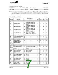
Test Conditions
Conditions
Symbol
Parameter
Min.
Typ.
Max.
Unit
VDD
DTMF Generator
VTDC
VTOL
VTAC
RL
0.45VDD
0.7VDD
DTMF Output DC Level
DTMF Sink Current
V
mA
¾
¾
¾
¾
¾
¾
¾
¾
¾
VDTMF=0.5V
0.1
120
5
¾
180
¾
DTMF Output AC Level
DTMF Output Load
155
¾
mVrms
kW
Row group, RL=5kW
THD£-23dB
ACR
THD
Column Pre-emphasis
Tone Signal Distortion
Row group=0dB
RL=5kW
1
2
3
dB
dB
¾
-30
-23
Functional Description
Execution Flow
each instruction. The conditional skip is activated by
instructions. Once the condition is met, the next instruc-
tion, fetched during the current instruction execution, is
discarded and a dummy cycle replaces it to get the
proper instruction. Otherwise proceed to the next in-
struction.
The system clock for the telephone controller is derived
from a 32768Hz crystal oscillator. Abuilt-in frequency up
conversion circuit provides dual system clock, namely;
32768Hz and 3.58MHz. The system clock is internally
divided into four non-overlapping clocks. One instruc-
tion cycle consists of four system clock cycles. Instruc-
tion fetching and execution are pipelined in such a way
that a fetch takes an instruction cycle while decoding
and execution takes the next instruction cycle. The
pipelining scheme causes each instruction to be effec-
tively executed in a instruction cycle. If an instruction
changes the program counter, two instruction cycles are
required to complete the instruction.
The program counter lower order byte register
(PCL:06H) is a readable and write-able register. Moving
data into the PCL performs a short jump. The destina-
tion will be within 256 locations. When a control transfer
takes place, an additional dummy cycle is required.
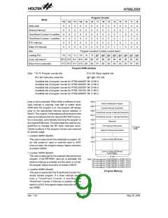
Program Memory - ROM
The program memory is used to store the program in-
structions which are to be executed. It also contains
data, table, and interrupt entries, and is organized into
8K´16 bits´2 banks (HT95L400/40P), 8K´16 bits
(HT95L300/30P, HT95L200/20P) or 4K´16 bits
(HT95L100/10P, HT95L000/00P), addressed by the
program counter and table pointer.
Program Counter - PC
The program counter (PC) controls the sequence in
which the instructions stored in the program ROM are
executed and its contents specify a full range of pro-
gram memory. After accessing a program memory word
to fetch an instruction code, the contents of the program
counter are incremented by 1. The program counter
then points to the memory word containing the next in-
struction code.
For the HT95L400/40P, the program memory is divided
into 2 banks, each bank having a ROM Size 8K´16 bits.
To move from the present ROM bank to a different ROM
bank, the higher 1 bits of the ROM address are set by
the BP (Bank Pointer), while the remaining 13 bits of the
PC are set in the usual way by executing the appropriate
jump or call instruction. As the 14 address bits are
latched during the execution of a call or jump instruction,
the correct value of the BP must first be setup before a
When executing a jump instruction, conditional skip ex-
ecution, loading PCL register, subroutine call, initial re-
set, internal interrupt, external interrupt or return from
subroutine, the program counter manipulates the pro-
gram transfer by loading the address corresponding to
T
1
T
2
T
3
T
4
T
1
T
2
T
3
T
4
T
1
T
2
T
3
T
4
S
y
s
t
e
m
C
l
o
c
k
P
C
P
C
+
1
P
C
+
2
P
C
F
e
t
c
h
I
N
S
T
(
P
C
)
E
x
e
c
u
t
e
I
N
S
T
(
P
C
-
1
)
F
e
t
c
h
I
N
S
T
(
P
C
+
1
)
E
x
e
c
u
t
e
I
N
S
T
(
P
C
)
F
e
t
c
h
I
N
S
T
(
P
C
+
2
)
E
x
e
c
u
t
e
I
N
S
T
(
P
C
+
1
)
Execution Flow
Rev. 1.20
8
May 26, 2004

 HOLTEK [ HOLTEK SEMICONDUCTOR INC ]