HT95LXXX
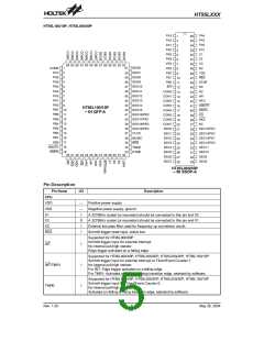
Pin Name
LCD Driver
I/O
Description
LCD panel segment outputs.
O
or
Some segment outputs can be optioned to Bidirectional input/output ports by software.
SEG47~SEG0
COM15~COM0
I/O
(See the ²LCD Driver² function)
LCD panel common outputs.
O
or
Some common outputs can be optioned to Bidirectional input/output ports by software.
(See the ²LCD Driver² function)
I/O
VLCD
I
LCD driver power source.
Normal I/O
Bidirectional input/output ports.
PA7~PA0
PB7~PB0
I/O Schmitt trigger input and CMOS output.
See mask option table for pull-high and wake-up function
Bidirectional input/output ports.
I/O Schmitt trigger input and CMOS output.
See mask option table for pull-high function
Bidirectional input/output ports.
Schmitt trigger input and CMOS output.
I/O
PD7~PD0
PE3~PE0
See mask option table for pull-high function
Port D could be optioned to LCD signal output, see the ²Input/Output Ports² function
Bidirectional input/output ports.
Schmitt trigger input and CMOS output.
I/O
See mask option table for pull-high function
Port E could be optioned to LCD signal output, see the ²Input/Output Ports² function
Bidirectional input/output ports.
PF7~PF0
PG3~PG0
I/O Schmitt trigger input and CMOS output.
See mask option table for pull-high function
Bidirectional input/output ports.
I/O Schmitt trigger input and CMOS output.
See mask option table for pull-high function
Dialer I/O (See the ²Dialer I/O Function²)
Schmitt trigger input structure. An external RC network is recommended for input
debouncing.
HFI
I
O
I
This pin is pulled low with internal resistance of 200kW typ.
HFO
HDI
CMOS output structure.
Schmitt trigger input structure. An external RC network is recommended for input
debouncing.
This pin is pulled high with internal resistance of 200kW typ.
HDO
HKS
O
I
CMOS output structure.
This pin detects the status of the hook-switch and its combination with HFI/HDI can con-
trol the PO pin output to make or break the line.
CMOS output structure controlled by HKS and HFI/HDI pins and which determines
whether the dialer connects or disconnects the telephone line.
PO
O
O
O
DNPO
NMOS output structure.
NMOS output structure. Usually, XMUTE is used to mute the speech circuit when trans-
mitting the dialer signal.
XMUTE
Peripherals
DTMF
This pin outputs dual tone signals to dial out the phone number. The load resistor should
O
not be less than 5kW.
MUSIC
LBIN
O
I
This pin outputs the single tone that is generated by the PFD generator.
This pin detects battery low through external R1/R2 to determine threshold voltage.
Rev. 1.20
6
May 26, 2004

 HOLTEK [ HOLTEK SEMICONDUCTOR INC ]