HT46R01B/02B/01N/02N
HT48R01B/02B/01N/02N
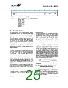
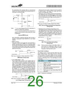
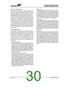
For applications that operate within an environment
where more noise is present the Enhanced Reset Cir-
cuit shown is recommended.
will ignore the low supply voltage and will not perform
a reset function. The actual VLVR value can be se-
lected via configuration options.
·
V
D
D
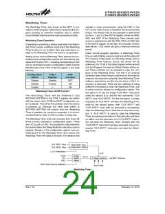
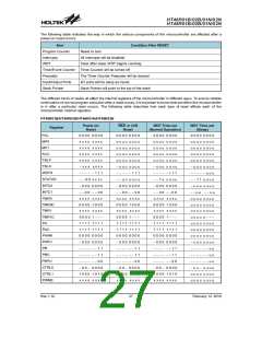
Watchdog Time-out Reset during Normal Operation
The Watchdog time-out Reset during normal opera-
tion is the same as a hardware RES pin reset except
that the Watchdog time-out flag TO will be set to ²1².
0
.
m
0
F
1
*
*
V
D
D
1
N
4
1
4
8
*
1
W
0 ~ k
W
D
T
T
i
m
e
-
o
u
t
1
0
W
0
k
t
R
S
T
t
S
D
S
+
T
R
E
S
/
P
A
I
n
t
e
r
n
a
l
R
e
s
e
t
3
W
0 * 0
0
.
1
m
F
~
1
Note: tRSTD is power-on delay, typical time=100ms
WDT Time-out Reset during Normal Operation
Timing Chart
V
S
S
Note:
²*² It is recommended that this component is
added for added ESD protection
·
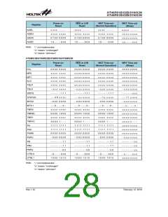
Watchdog Time-out Reset during Sleep mode
The Watchdog time-out Reset during Sleep mode is a
little different from other kinds of reset. Most of the
conditions remain unchanged except that the Pro-
gram Counter and the Stack Pointer will be cleared to
²0² and the TO flag will be set to ²1². Refer to the A.C.
Characteristics for tSST details.
²**² It is recommended that this component is
added in environments where power line noise
is significant
External RES Circuit
W
D
T
T
i
m
e
-
o
u
t
More information regarding external reset circuits is
located in Application Note HA0075E on the Holtek
website.
t
S
S
T
I
n
t
e
r
n
a
l
R
e
s
e
t
·
RES Pin Reset
WDT Time-out Reset during Sleep
Timing Chart
This type of reset occurs when the microcontroller is
already running and the RES pin is forcefully pulled
low by external hardware such as an external switch.
In this case as in the case of other reset, the Program
Counter will reset to zero and program execution initi-
ated from this point.
Note: The tSST can be chosen to be either 1024 or 2
clock cycles via configuration option if the sys-
tem clock source is provided by ERC or HIRC.
The SST is 1024 for HXT or LXT.
0
.
D
9
D
V
0
.
D
4
D
V
Reset Initial Conditions
R
E
S
t
R
S
T
t
S
D
S
The different types of reset described affect the reset
flags in different ways. These flags, known as PDF and
TO are located in the status register and are controlled
by various microcontroller operations, such as the Sleep
function or Watchdog Timer. The reset flags are shown
in the table:
I
n
t
e
r
n
a
l
R
e
s
e
t
Note: tRSTD is power-on delay, typical time=100ms
RES Reset Timing Chart
·
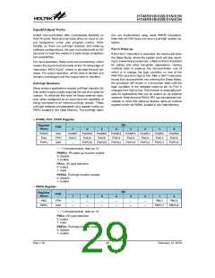
Low Voltage Reset - LVR
The microcontroller contains a low voltage reset cir-
cuit in order to monitor the supply voltage of the de-
vice. The LVR function is selected via a configuration
option. If the supply voltage of the device drops to
within a range of 0.9V~VLVR such as might occur when
changing the battery, the LVR will automatically reset
the device internally. For a valid LVR signal, a low sup-
ply voltage, i.e., a voltage in the range between
0.9V~VLVR must exist for a time greater than that spec-
ified by tLVR in the A.C. characteristics. If the low sup-
ply voltage state does not exceed this value, the LVR
TO PDF
RESET Conditions
Power-on reset
0
u
0
u
RES or LVR reset during Normal or Slow
Mode operation
WDT time-out reset during Normal or
Slow Mode operation
1
1
u
1
WDT time-out reset during Sleep Mode
operation
Note: ²u² stands for unchanged
L
V
R
t
R
S
T
t
S
D
S
+
T
I
n
t
e
r
n
a
l
R
e
s
e
t
Note: tRSTD is power-on delay, typical time=100ms
Low Voltage Reset Timing Chart
Rev.1.10
26
February 12, 2010

 HOLTEK [ HOLTEK SEMICONDUCTOR INC ]