HT46R01B/02B/01N/02N
HT48R01B/02B/01N/02N
·
·
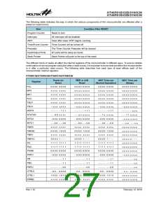
The I/O ports will maintain their present condition.
system power-up or executing the clear Watchdog
Timer instructions and is set when executing the
²HALT² instruction. The TO flag is set if a WDT time-out
occurs, and causes a wake-up that only resets the Pro-
gram Counter and Stack Pointer, the other flags remain
in their original status.
In the status register, the Power Down flag, PDF, will
be set and the Watchdog time-out flag, TO, will be
cleared.
Standby Current Considerations
As the main reason for entering the Sleep Mode is to
keep the current consumption of the MCU to as low a
value as possible, perhaps only in the order of several
micro-amps, there are other considerations which must
also be taken into account by the circuit designer if the
power consumption is to be minimised.
Pins PA0 to PA7 can be setup via the PAWK register to
permit a negative transition on the pin to wake-up the
system. When a PA0 to PA7 pin wake-up occurs, the pro-
gram will resume execution at the instruction following
the ²HALT² instruction.
If the system is woken up by an interrupt, then two possi-
ble situations may occur. The first is where the related
interrupt is disabled or the interrupt is enabled but the
stack is full, in which case the program will resume exe-
cution at the instruction following the ²HALT² instruction.
In this situation, the interrupt which woke-up the device
will not be immediately serviced, but will rather be ser-
viced later when the related interrupt is finally enabled or
when a stack level becomes free. The other situation is
where the related interrupt is enabled and the stack is
not full, in which case the regular interrupt response
takes place. If an interrupt request flag is set to ²1² be-
fore entering the Sleep Mode, then any future interrupt
requests will not generate a wake-up function of the re-
lated interrupt will be ignored.
Special attention must be made to the I/O pins on the
device. All high-impedance input pins must be con-
nected to either a fixed high or low level as any floating
input pins could create internal oscillations and result in
increased current consumption. Care must also be
taken with the loads, which are connected to I/O pins,
which are setup as outputs. These should be placed in a
condition in which minimum current is drawn or con-
nected only to external circuits that do not draw current,
such as other CMOS inputs.
If the configuration options have enabled the Watchdog
Timer internal oscillator LIRC then this will continue to
run when in the Sleep Mode and will thus consume
some power. For power sensitive applications it may be
therefore preferable to use the system clock source for
the Watchdog Timer. The LXT, if configured for use, will
also consume a limited amount of power, as it continues
to run when the device enters the Sleep Mode. To keep
the LXT power consumption to a minimum level the
LXTLP bit in the CTRL0 register, which controls the low
power function, should be set high.
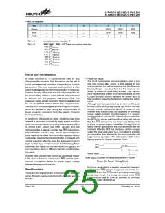
No matter what the source of the wake-up event is, once
a wake-up event occurs, there will be a time delay be-
fore normal program execution resumes. Consult the ta-
ble for the related time.
Oscillator Type
Wake-up
Source
ERC, IRC
Crystal
Wake-up
External RES
PA Port
tRSTD + tSST1
tRSTD + tSST2
After the system enters the Sleep Mode, it can be woken
up from one of various sources listed as follows:
tSST1
tSST2
Interrupt
·
·
·
·
An external reset
WDT Overflow
An external falling edge on PA0 to PA7
A system interrupt
Note: 1. tRSTD (reset delay time), tSYS (system clock)
2. tRSTD is power-on delay, typical time=100ms
3. tSST1= 2 or 1024 tSYS
A WDT overflow
If the system is woken up by an external reset, the de-
vice will experience a full system reset, however, if the
device is woken up by a WDT overflow, a Watchdog
Timer reset will be initiated. Although both of these
wake-up methods will initiate a reset operation, the ac-
tual source of the wake-up can be determined by exam-
ining the TO and PDF flags. The PDF flag is cleared by a
4. tSST2= 1024 tSYS
Wake-up Delay Time
Rev.1.10
23
February 12, 2010

 HOLTEK [ HOLTEK SEMICONDUCTOR INC ]